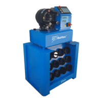
The Balflex P20/P32 is an electrically operated hydraulic crimping machine designed for crimping hose fittings. It comprises a crimping head and a hydraulic unit mounted on an oil tank, which also serves as the machine frame. The P32 version is typically delivered with a 3-phase electric motor of 4kW, while the P20 version uses a 3kW motor. Both versions can be equipped with a single-phase motor upon request. The machine is intended for professional use and should be operated in room temperature, dry indoor conditions, and with sufficient illumination.
Function Description
The primary function of the Balflex P20/P32 is to crimp hose fittings by applying hydraulic pressure. The machine operates in a semi-automatic mode, where the crimping movement starts once the master dies have reached a set retraction position. The dies close when the crimping push-button is depressed and continue until the button is released or the preset crimping diameter is reached. Conversely, the dies open when the retraction button is depressed and held down, until the button is released or the maximum retraction is reached. A signal lamp illuminates when the dies have reached either the set crimping diameter or the set retraction diameter. The machine is equipped with an emergency stop button that halts all functions when pressed, which can be released by turning it clockwise.
Important Technical Specifications
The P20 and P32 models have distinct size and weight specifications:
- P20 Machine:
- Length (X): 760 mm
- Width (Y): 600 mm
- Height (Z): 810 mm
- Gross Weight: 190 kg
- Net Weight: 155 kg
- P20 Die Rack:
- Length (X): 660 mm
- Width (Y): 340 mm
- Height (Z): 800 mm
- P32 Machine:
- Length (X): 760 mm
- Width (Y): 600 mm
- Height (Z): 810 mm
- Gross Weight: 280 kg
- Net Weight: 225 kg
- P32 Die Rack:
- Length (X): 660 mm
- Width (Y): 340 mm
- Height (Z): 800 mm
The oil tank volume for both models is 32 liters, with Shell Tellus T46 or equivalent hydraulic oil recommended. The crimping diameter dial covers a range of 0-10 mm, with a measuring scale divided into divisions of either 0.01 mm or 0.1 mm. Each full clockwise turn of the adjusting knob adds 1 mm to the crimping diameter.
The machine is designed to comply with several standards and directives, including:
- Standards: ISO 13850, EN 60204-1, EN 693, EN ISO 12100-1, EN ISO 12100-2.
- Directives: 2006/42/EEC, 2006/95/EEC, 2004/108/EEC.
Usage Features
- Die Set Selection: The machine uses original Balflex die sets, each with a specific crimping range. The minimum crimping diameter (D) is marked on each die set. Die charts are provided to assist in selecting the correct die set and corresponding dial adjustment values based on the fitting manufacturer's specifications.
- Die Set Installation (Quick Change): The Quick Change Tool Base allows for storing die sets under the machine. Dies are installed one set at a time using a quick change tool. It is crucial to ensure master dies are clean and the motor is stopped before installation. The dies should be opened to maximum retraction, the tool inserted into the die set, turned clockwise, and the set pulled out. When mounting, the die set is placed between master dies, and the dies are closed completely until the pins are locked.
- Single Die Change (P20, P32): For changing a single die, the motor must be stopped after reaching maximum retraction. Contact surfaces of both the die set and master dies must be clean. A pull pin in the master die is pulled with a special tool, the new die inserted with the retaining pin (die number facing the operator), and the pull pin released. After installing all dies, they should be straight and properly seated.
- Crimping Diameter Setting (MS Control): The crimping diameter is set using a Vernier dial. The dial is factory-calibrated so that a setting of 0.0 corresponds to the minimum diameter of the installed die set. The dial's adjusting knob increases the crimping diameter by 1 mm per full clockwise turn.
- Retraction Diameter Control: A separate dial adjusts the retraction diameter of the master dies after the crimping cycle. This allows for easy insertion of the fitting while minimizing extra movement. Turning the dial clockwise increases the retraction.
- Safety Features:
- Warning 1: Do not put hands inside the dies while the motor is running.
- Warning 2: Hold the hose far enough to avoid crimping hands during operation.
- Warning 3: Do not touch the hand emergency push-buttons during normal operation.
- Warning 4: High voltage. The electric box should only be opened by a professional electrician.
- Warning 5 (P32 model): Do not remove the housing covering the rear of the crimping head, as it protects against crimping hazards.
- Warning 7: When changing dies with the quick change tool, hold the handle as shown in the figures to prevent hands from getting between the dies.
- Emergency Stop: A prominent emergency stop button immediately halts all machine functions.
Maintenance Features
- Preventive Maintenance: Routine maintenance can be performed by the operator, but electrical work and repairs involving seals or the pump must be carried out by a qualified specialist. Before any servicing, the supply disconnecting device must be turned to '0', and the plug or supply cable disconnected from the mains before changing the motor circuit breaker or undervoltage trip. Dies should be opened to maximum retraction before servicing.
- Greasing (P20, P32): The inner surface of the conical flanges and the master dies should be lubricated daily with pressure-proof grease (e.g., Optimol Viscogen 4). Grease should be applied to the conical surfaces at the front and back of the die with a small brush. The piston rod should not be greased.
- Oil Change: The oil tank should be emptied via the drain plug. Waste oil must be handled according to local regulations. The tank is refilled to the center line of the dipstick indicators with hydraulic oil (Shell Tellus T46 or equivalent). Hydraulic oil should be changed after the first 500 hours of operation and every 1000 hours thereafter. It is recommended to pump new oil through a 20 μ filter.
- Filter Change (P20, P32): The tank cover is opened and kept open with a block of wood. The filter insert is unscrewed and removed. The old filter must be handled according to law. The seal of the new filter insert is lubricated with hydraulic oil before screwing it on. The filter insert must be changed concurrently with the oil.
- Re-calibration of Crimping Diameter Dial (MS Control): The crimping diameter dial is factory-calibrated. If re-calibration is needed, a ferrule (seamless steel tube, Ø 25 mm, wall 2 mm) is used with a specific die set (P20/19 or P32/19). The dial is set to 1.0 (for a 20 mm crimping diameter), the ferrule is crimped, and the real diameter measured. The control dial is then removed (without turning the shaft), the dial lock opened, the real diameter set, relocked, and the dial reinstalled. This process is repeated until the dial accurately reflects the crimping diameter. After adjustment, the dial at 0.0 should correspond to the minimum nominal crimping diameter of each die set.