55
55
english
Read times from
Data carrier to
processor in
dynamic mode
(parametering:
2nd byte, bit 5 = 1,
without CRC_16 data
check)
Read times within the 1st block for dual read and compare:
The indicated times apply after the Data carrier has been recognized. If the Data carrier is not
yet recognized, an additional 45 ms for building the required energy field until the Data carrier is
recognized must be added.
Formula: t = (m + 1)
*
3.5 ms
Example: Read 11 bytes starting at address 9, i.e. the highest address to be read is 19.
This corresponds to 70 ms.
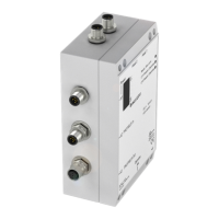
Read/Write Times
m = highest address to be read
Data carrier with 32 byte blocks Data carrier with 64 byte blocks
No. of bytes Read time [ms] No. of bytes Read time [ms]
from 0 to 3 14 from 0 to 3 14
for each additional
byte add 3.5
for each additional
byte add 3.5
from 0 to 31 112 from 0 to 63 224
C60_2-019_818217_0806-e.p65
56
english56
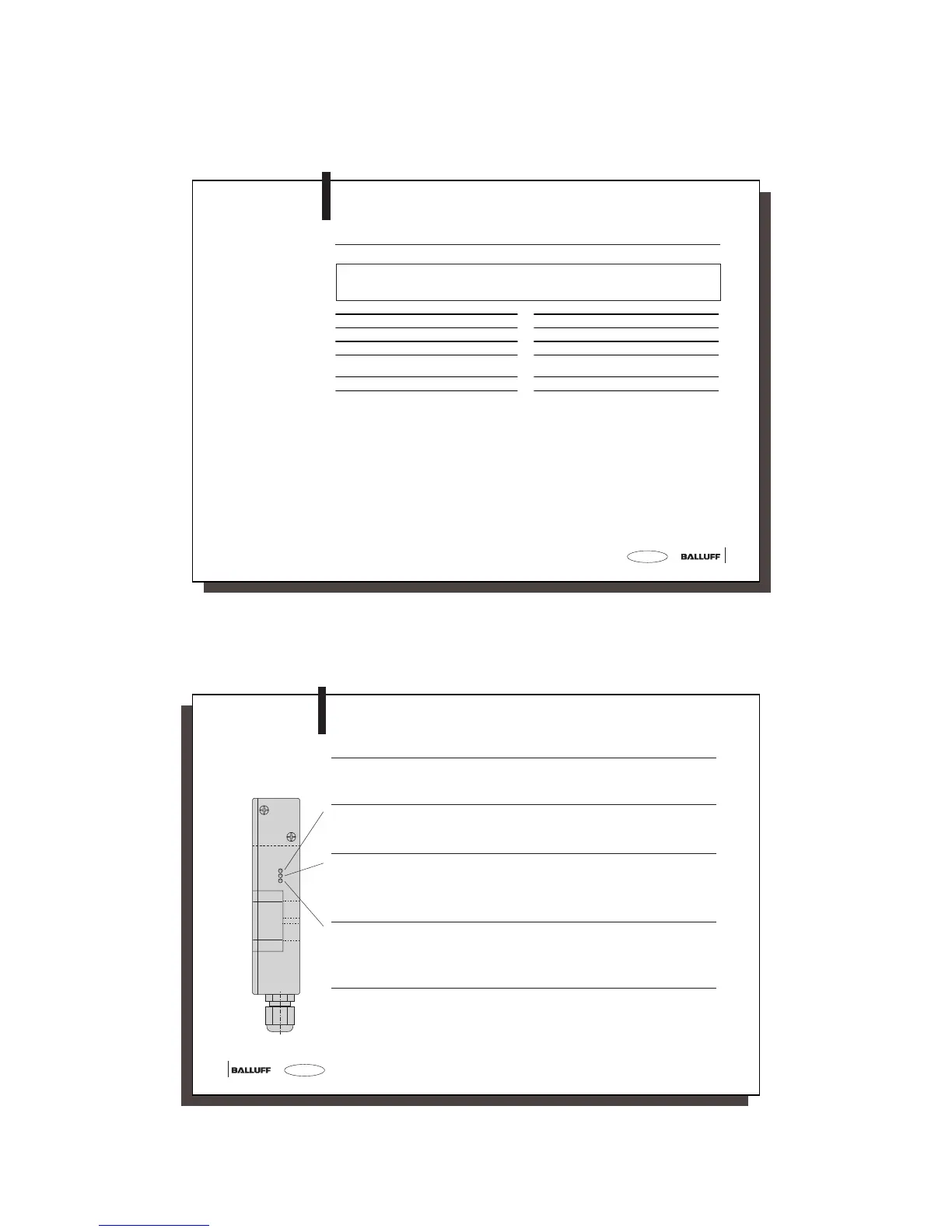
Function displays
on BIS C-60_2
The BIS C-60_2 uses the three side-mounted LED's to indicate important conditions of the
identification system.
Status LED Meaning
Ready / Bus active red Supply voltage OK; no hardware error,
however, bus not active.
green Supply voltage / hardware OK,
bus active.
CT1 Present / operating green Data carrier read/write-ready at read/write head 1.
yellow Read/write command at read/write head 1 in
process.
yellow flashes Cable break to read/write head or not connected.
off No Data carrier in read/write range of
read/write head 1.
CT2 Present / operating green Data carrier read/write-ready at read/write head 2.
yellow Read/write command at read/write head 2 in
process.
yellow flashes Cable break to read/write head or not connected.
off No Data carrier in read/write range of
read/write head 2.
If all three LED's are synchronously flashing, it means a hardware error. Return the unit to the factory.
LED Display