15
15
english
Input and Output
Buffers
In order to transmit commands and data between the BIS C-60_2 and the host system, the
latter must prepare two fields. These two fields are:
– the output buffer
for the control commands which are sent to the BIS Identification System and
for the data to be written.
– the input buffer
for the data to be read and
for the designators and error codes which come from the BIS Identification System.
The possible setting values are stored in the GSD file.
The buffer size can be selected between 4 and 128 bytes in steps of 2 bytes. This must be
given by the master during parametering. The total buffer size is divided into 2 ranges:
Buffer range 1 for Read/Write Head 1; size is specified in paramter byte 6.
Buffer range 2 for Read/Write Head 2; size = total buffer size – buffer size of Read/Write
Head 1. See
16 for example.
If a buffer size of less than 6 bytes (8 bytes with double bit header) is set for a read/write head, a
read/write request can be carried out without specifying the start address and the number of
bytes. Automatic reading for Codetag-Present (see
30) remains active. This permits fast
reading of small data quantities without placing an unnecessary load on the bus.
Buffer size – 1 = number of bytes read without double bit header;
Buffer size – 2 = number of bytes read with double bit header.
☞
Function Description
Input and Output Buffers
Please note the
basic procedure on
14 and 29...35
and the examples on
pages
36...53.
C60_2-019_818217_0806-e.p65
16
english16
Function Description
Input and Output Buffers
☞
Example: The 82 bytes for the total buffer need to be distributed. An input/output buffer of
46 bytes is assigned to Read/Write Head 1. This results in an input/output buffer of 36 bytes
for Read/Write Head 2.
Procedure: The buffer size for Read/Write Head 1 is set to 46 bytes. This means using the
parameter byte 6 to enter Hex value 2E (corresponds to 46 decimal), which corresponds to
binary 00101110.
PLC Organisation: The buffer range starts at input byte IB 32 and output byte OB 32.
Result:
Read/Write Head 1: Subaddress 00 IB 32 and OB 32
(R/W 1) Input buffer IB 32 to IB 77
Output buffer OB 32 to OB 77
Read/Write Head 2: Subaddress 00 IB 78 and OB 78
(R/W 2) Input buffer IB 78 to IB 113
Output buffer OB 78 to OB 113
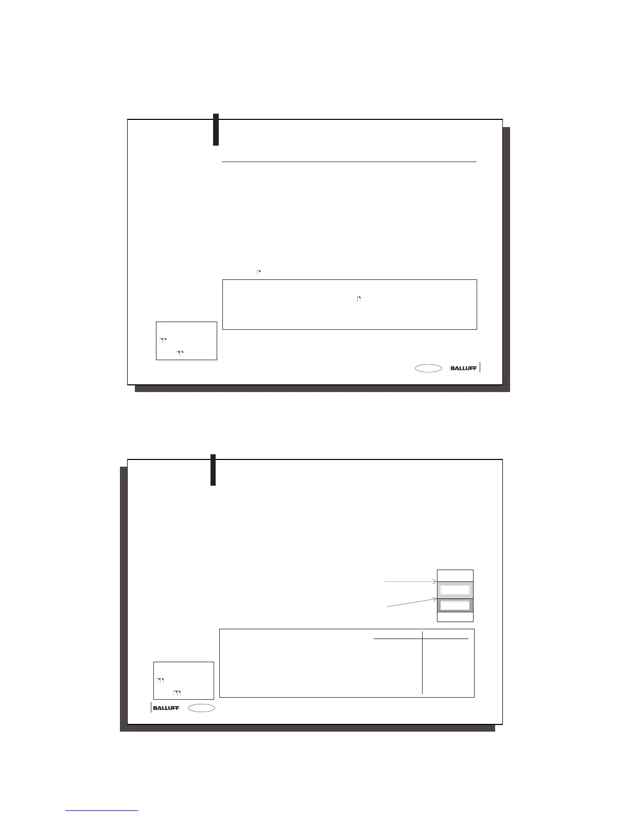
IB 0 / OB 0
PLC buffer
Buffer for R/W 1
Buffer for R/W 2
Input and Output
Buffers
(continued)
Note that these buffers can be in two different
sequences depending on the type of control.
The following description is based on sequence 1!
Sequence 1 Sequence 2
Subaddress 00 Subaddress 01
01 00
02 03
03 02
04 05
05 04
06 07
07 06
Please note the
basic procedure on
14 and 29...35
and the examples on
pages
36...53.