59
59
english
BIS C-6002-...-KL2
Installing the connection cables
The BIS C-6002 processor must be opened in order to make the connections for the supply
voltage, the digital input and the PROFIBUS connections (see
58).
First be sure that the unit is disconnected from power.
Remove the 4 screws on the BIS C-6002 and lift off the cover.
Guide the two PROFIBUS cables through the PG 11 fittings (see
60). For additional infor-
mation on wiring, see the following
.
Push the cable for supply voltage and for the digital input through the PG 9 fitting.
Close up the processor.
If the processor is equipped with an adapter:
– BIS C-650: Connect the read/write heads to terminals Head 1 and Head 2.
– BIS C-670: Connect the read/write head to terminal Head 1.
Make connections
on the BIS C-6002
processor
C60_2-019_818217_0806-e.p65
60
english60
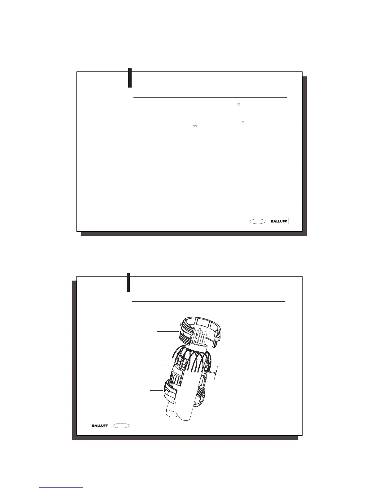
Connecting the
shield of the
PROFIBUS-DP cable
in the PG 11 housing
on the processor
BIS C-6002
BIS C-6002-...-KL2
Mounting the PG Connection for PROFIBUS-DP
After connecting the (field) bus leads to the termional block, make sure that the shield has
proper connection to the PG housing.
Screw socket
Inside O-ring
Cable clamp
Screw the
swivel nut
with a torque
of 4.17 Nm
ca. 3 - 4 mm