www.balluff.com 9english
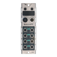
4.3 Display elements
Fig. 4-3:
DIO
XF2XF1
LINK
ACT
LINK
ACT
BF
ERR
SF
RUN
X01
X02
01
00
01
00
UAUS
BNI XG3-508-0C5-Z015
BNI00K8
Status LEDs
Port/Pin LEDs:
Status of IO-Link and
I/O-Ports
Display elements
Port/Pin LEDs
– LED00 – Port-Pin 4
– LED01 – Port-Pin 2
Port/Pin LEDs Standard Port
Signal Meaning
Off State of input or output pins is 0
Yellow State of input or output pins is 1
Both LEDs
red flashing
Short circuit of sensor supply between
pin1 and pin3
Red Short circuit at output on pin2/4 against
pin3
Red No high signal at diagnostic input
Red 24 V input signal on configured output
(actuator warning)
Tab. 4-1: LEDs Standard Port
Port/Pin LEDs IO-Link Port
Signal Meaning
Green IO-Link connection active
Green
flashing
No IO-Link connection or incorrect
IO-Link device
Green, fast
flashing
IO-Link: Preoperate during data storage
Red, fast
flashing
Validation failed / incorrect configuration
of the IO-Link data length
Red, fast
flashing
Data storage failed / incorrect device for
data storage
Red IO-Link: Short circuit of pin4 against
pin3
Tab. 4-2: LEDs IO-Link Port
Status LEDs
BNI PG3-508-0C5-Z015 (Profinet)
LED Signal Meaning
US Green Input voltage OK
Red flashing Input voltage low (<18V)
UA Green Output voltage OK
Red flashing Output voltage low (<18V)
Red No output voltage present
(<11V)
SF Off No error
Red Watchdog timeout; channel,
general or extended diagnostics
present; system error
Red flashing Service DCP signal started via
bus
BF Off No error
Red Low speed of physical link; or no
physical link
Red flashing No data exchange or no
configuration
100 Off Transmission rate: 10Mbit/s
Yellow Transmission rate: 100Mbit/s
LK1/2 Green
flashing
Data transfer
Tab. 4-3: Status LEDs Profinet
4
Product description (continued)
BNI _ G3-508-0C5-Z015
Network interface
 Loading...