8 english
5.1 Installation
For dimensions, see Fig. 4-1 on page7.
CAUTION
Red light / infrared light
If you look into the light beam emitted by the transmitter,
temporary blinding and irritation of the eyes is possible.
► Locate transmitter units so that it is not possible to
look into the light beam even during operation.
Installation instructions
– The sensor can be fastened with two M3 screws.
– The installation location must be free of vibrations,
dust, toxic vapors, water, oil and chemicals.
– Do not install the sensor in the open or near inductive
devices or sources of heat.
– Do not expose the sensor to direct sunlight or other
direct sources of light.
– The max. cable length is 100m with a line cross-
section of min. 0.3mm
2
.
– Do not install the connection cable parallel to high-
voltage or motor cables.
5
Installation and connection
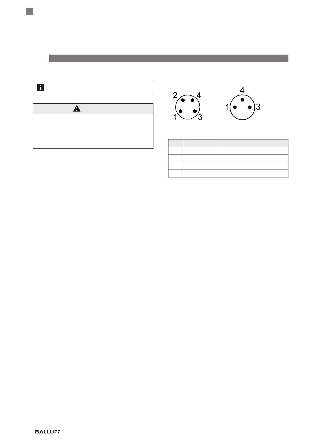
5.2 Electrical connection
S75 plug S49 plug
Fig. 5-1: Pin assignment of plug variant (top view of pin side)
Pin Wire color Signal
1 BN UB+ (10…30VDC)
2 WH Not used
3 BU UB− (0V)
4 BK OUT1 (switch output)
Tab. 5-1: Pin assignment
BOS R090K-_U-_ D1_-S49/S75/02
Photoelectric sensors – Diffuse sensors
 Loading...