Do you have a question about the Balluff BTL5-T1 M P-S103 Series and is the answer not in the manual?
| Brand | Balluff |
|---|---|
| Model | BTL5-T1 M P-S103 Series |
| Category | Accessories |
| Language | English |
Describes construction, function, and setup options for the BTL sensor with Profibus DP interface.
Explains action sequences, notes, and tips used in the guide for clarity and user guidance.
Lists included mounting clamps and condensed guide. Notes magnets must be ordered separately.
Informs about GSD file availability via download from the internet or email.
Lists UL approval, US patent, CE mark, and product standards met by the BTL sensor.
Defines the BTL sensor's application as a position measuring system in industrial environments.
Provides essential safety guidelines for installation, startup, and operation by trained personnel.
Details signal words (NOTICE, DANGER) and symbols used to communicate hazards and safety measures.
Advises to observe national regulations for the proper disposal of the product.
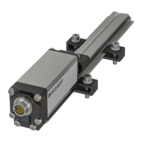
Describes the sensor's housing, electrical connection, magnet interaction, and available nominal lengths.
Explains how the sensor generates a torsional wave from a magnet's field and converts it into an electrical signal.
Specifies that up to 4 magnets can be used, with a minimum distance requirement between them.
Covers proper mounting, orientation, and clamp usage to prevent damage and ensure proper function.
Details installation notes for captive magnets, including avoiding lateral forces and connecting to machine members.
Provides guidelines for installing floating magnets, including distance requirements and offset values.
Covers EMC requirements, proper cable routing, and noise elimination for reliable data transmission.
Details pin assignments for supply voltage, control/data signals, and provides a connection example.
Outlines steps for safe system startup, emphasizing checking connections and potential uncontrolled movements.
Advises regular checks, taking the device out of operation during malfunctions, and securing the system.
Lists the factory default settings for station address, resolution, and maximum working range.
Explains setting the station address and bus termination using DIP switches, and details the LED display for Profibus encoder profile.
Details typical values for position resolution, non-linearity, hysteresis, reproducibility, and temperature coefficient.
Specifies operating and storage temperature ranges, and relative humidity limits.
Lists specifications for stabilized voltage, residual ripple, current draw, and protection features.
Defines the standard for control signals (RxD/TxD-N, RxD/TxD-P, Data GND) as per EN 50170.
States the maximum number of magnets that can be used with the sensor.
Provides nominal length range and typical weight and housing material information.
Specifies the maximum length of the field bus cable and mentions shielded, twisted-pair connections.
Details installation dimensions and specifications for various captive magnet models.
Provides technical details and installation dimensions for the joint rod accessory.
Shows installation dimensions and specifications for different floating magnet types.
Lists and describes various freely configurable and preassembled connectors and connecting cables for system integration.
Provides conversion tables for millimeters to inches and inches to millimeters.
Illustrates an example of the BTL5 part label with order code, type, and serial number.

