www.balluff.com 7english
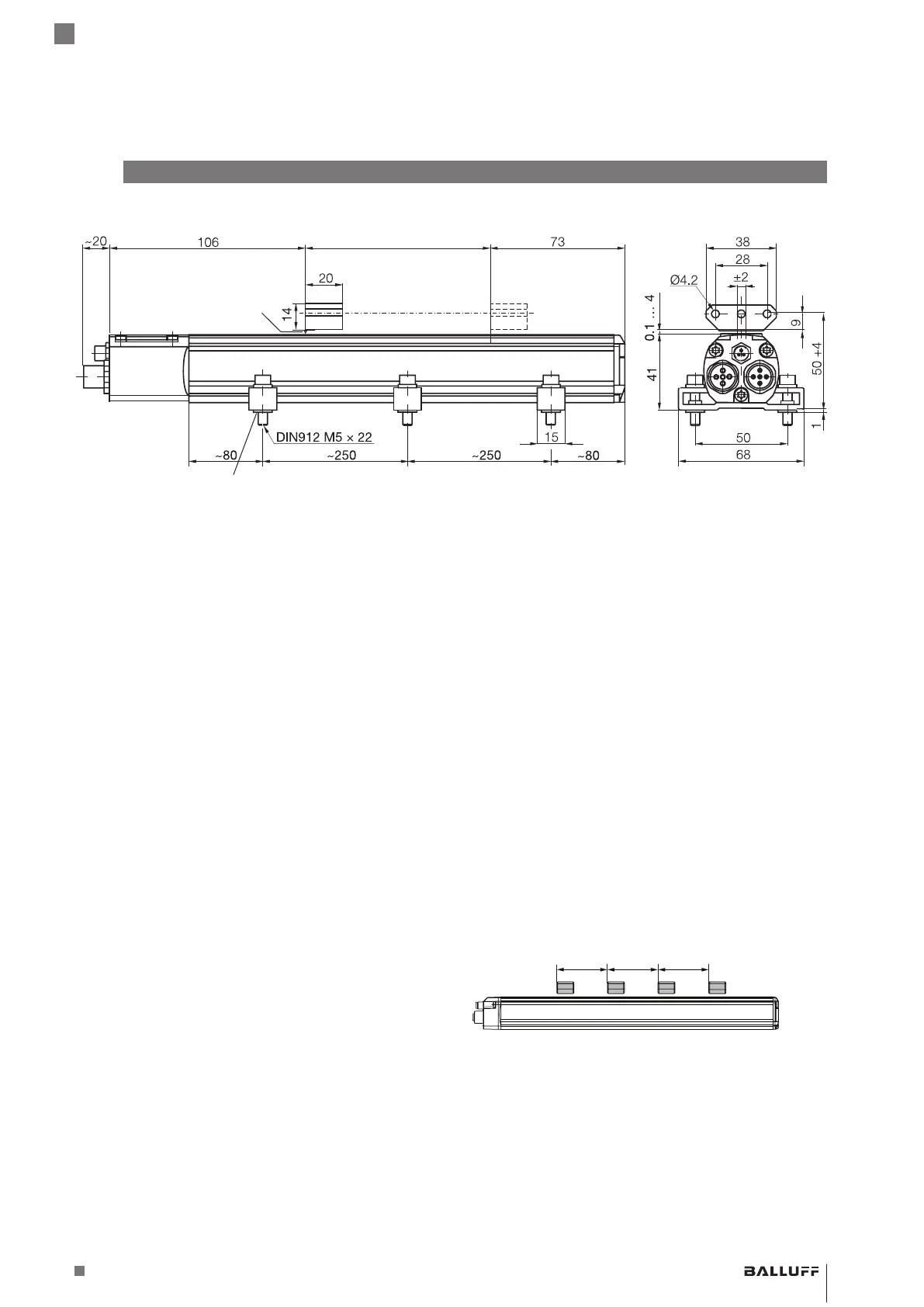
1) Unusable area
2) Not included in scope of delivery
3) Groove on the top side of the profile marks the start of
measuring range
1)
Nominal length =
measuring range
BTL5-P-3800-2
magnet
1)
Mounting clamps with insulating bushes and
ISO4762M5x22 cylinder head screws, max.
tightening torque 2Nm
2)
3)
Null point
Groove
End point
Fig. 3-1: BTL5…, construction
3
Construction and function
The component of the torsional wave which arrives at the
end of the waveguide is absorbed in the damping zone to
prevent reflection. The wave generated at position of the
magnet returns to the head end of the BTL where a coil
converts the wave into an electrical signal. The travel time
of the wave is used to calculate the position at a resolution
of 5µm. This is done with high precision and reproducibility
within the measuring range designated as the rated length.
The electrical connection between the BTL, evaluation
unit/controller, and power supply is established via several
cables that are connected via connectors.
3.3 Number of magnets
Up to 4 magnets can be used. The distance (L) between
the magnets must be at least 65mm.
Fig. 3-2:
L L L
Distance between the magnets
3.1 Construction
Electrical connection: The electrical connection is made
via a cable (see Type code on page19).
Housing: Stainless steel housing containing the
processing electronics.
Magnet: Defines the position to be measured on the
waveguide. Magnets are available in various models and
must be ordered separately (see Accessories on
page15).
Nominal length: To optimally adapt the BTL to the
application, nominal lengths from 50mm to 4000mm are
available.
3.2 Function
The BTL contains the waveguide which is protected by an
aluminum housing. A magnet is moved along the
waveguide. This magnet is connected to the system part
whose position is to be determined.
The magnet defines the position to be measured on the
waveguide.
An internally generated INIT pulse interacts with the
magnetic field of the magnet to generate a torsional wave
in the waveguide which propagates at ultrasonic velocity.
BTL5-T1 __ -M ____ -P-S103
Magnetostrictive Linear Position Sensor – Profile Style

 Loading...