Do you have a question about the Balluff BTL5 Series and is the answer not in the manual?
This guide describes the construction, function, and setup options for the BTL5 magnetostrictive linear position sensor.
Explains symbols and numbering used in the instructions for clarity and consistency in technical documentation.
Lists the items included in the BTL product package and any separately ordered accessories.
Details certifications like CE, UL, and patent information relevant to product compliance.
Specifies the intended application of the BTL sensor within industrial measurement systems.
Provides essential safety precautions for installation, startup, and operation by qualified personnel.
Clarifies the meaning of signal words (DANGER, NOTICE) and symbols used in safety warnings.
Advises users to adhere to national regulations for the environmentally sound disposal of the product.
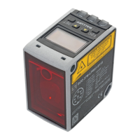
Details the physical components, mounting threads, and housing of the BTL sensor.
Explains the working principle of the magnetostrictive sensor, including waveguide and torsional waves.
Specifies the maximum number of magnets usable and the minimum distance required between them.
Provides instructions for installing the BTL sensor in both non-magnetizable and magnetizable materials.
Covers essential preparation steps like horizontal assembly, hydraulic cylinder considerations, and mounting threads.
Details the process of physically installing the BTL sensor, including mounting and cable outlet direction.
Offers specific advice for installing the BTL in hydraulic cylinders, including slide elements and magnet placement.
Explains how to make the electrical connection, referencing pin assignments and cable/connector types.
Covers critical aspects of EMC compliance, including grounding, shielding, and proper cable management.
Outlines the procedure for safely starting up the position measuring system, including checks and parameter adjustments.
Provides guidelines for regular checks, malfunction handling, and securing the system during operation.
Details the accuracy specifications such as position resolution, linearity deviation, and hysteresis.
Lists environmental operating limits, including temperature, humidity, and pressure ratings.
Specifies the required external supply voltage, ripple limits, and current draw.
Describes the electrical signals used for control and output, including INIT pulse and Start/Stop levels.
Indicates the maximum number of magnets supported by the system.
Provides physical dimensions, rod diameters, nominal lengths, and weight information for the sensor.
Details various magnet models available as accessories for the BTL sensor, including specifications.
Lists available connectors and cables that can be used with the BTL sensor for electrical connection.
Provides conversion tables for units of length between millimeters and inches.
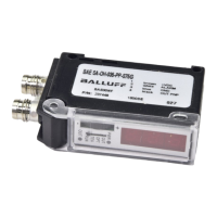
Shows an example of the product's part label, identifying key information like order code and serial number.
| Series | BTL5 |
|---|---|
| Product Category | Accessories |
| Length | Varies with model |
| Width | Varies with model |
| Thickness | Varies with model |
| Type | Magnet |