www.balluff.com 17deutsch
8
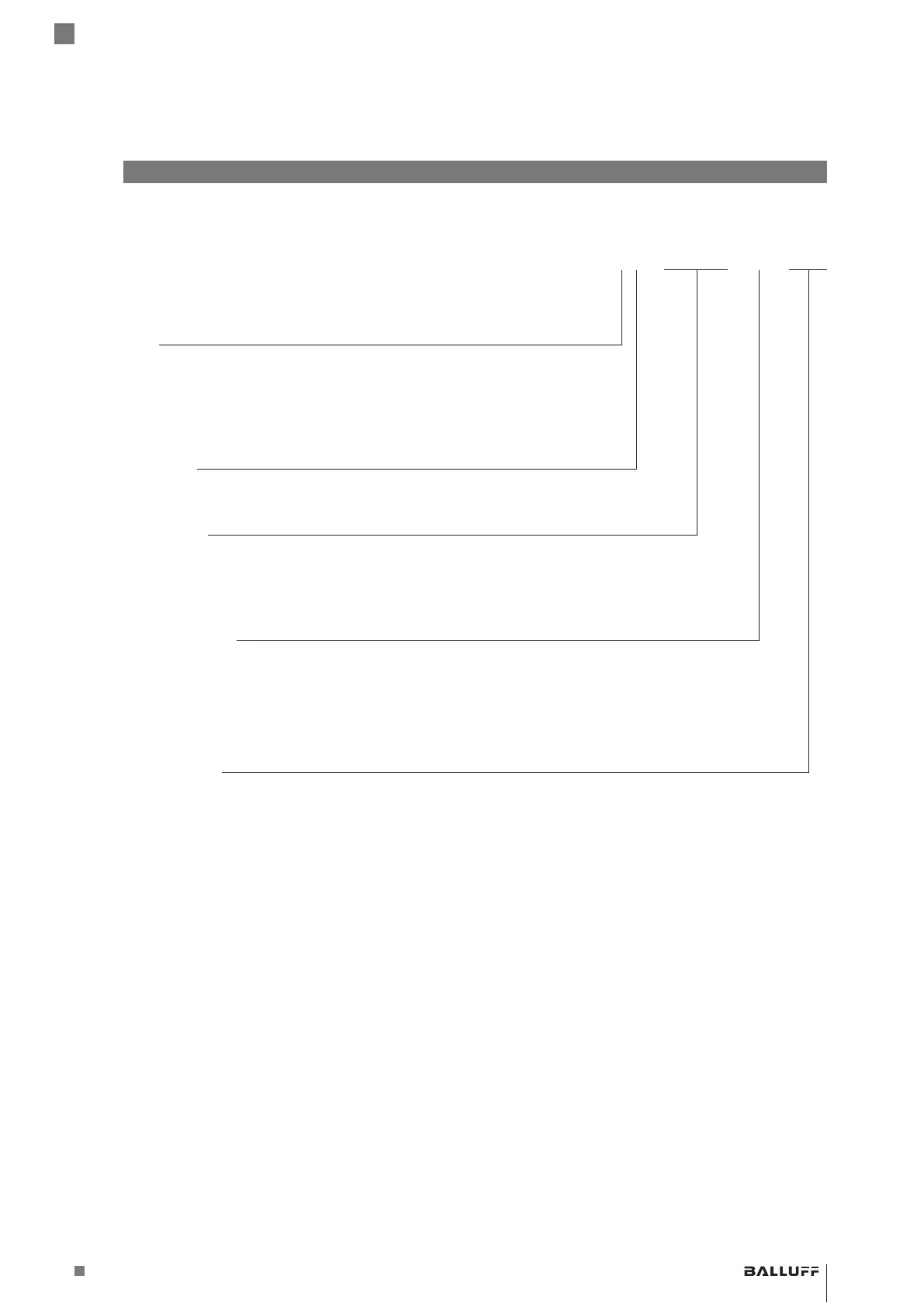
Typenschlüssel
BTL5 - P1 - M0500 - H - S32
Schnittstelle:
P = Start/Stop, 2. Flanke aktiv
I = Start/Stop, Tri-State, 2. Flanke aktiv
L = Tor
M = Start/Stop, 1. Flanke aktiv
Betriebsspannung:
1 = 20…28VDC
Nennlänge (4-stellig):
M0500 = metrische Angabe in mm, Nennlänge 500mm
(H8/W8: M0025…M1016)
(H/W: M0025…M5500)
Stabversion, Befestigung:
H = metrisches Befestigungsgewinde M18×1.5, O-Ring, Stabdurchmesser 10,2mm
W = Zollgewinde 3/4"-16UNF, O-Ring, Stabdurchmesser 10,2mm
H8 = metrisches Befestigungsgewinde M18×1.5, O-Ring, Stabdurchmesser 8mm
W8 = Zollgewinde 3/4"-16UNF, O-Ring, Stabdurchmesser 8mm
Elektrischer Anschluss:
S32 = 8-polig, M16-Stecker nach IEC130-9
KA05 = Kabel 5m, axial (PUR)
K05 = Kabel 5m, radial (PUR)
BTL5-P/I/L/M1-M ____ -H/W(8) -S32/KA __ /K __
Magnetostriktives Positionsmesssystem – Bauform Stab
 Loading...