www.balluff.com 17english
8
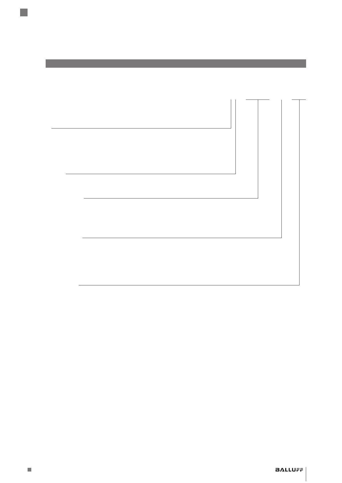
Type code
BTL5 - P1 - M0500 - H - S32
Interface:
P = Start/Stop, 2nd edge active
I = Start/Stop, tri-state, 2nd edge active
L = Tor
M = Start/Stop, 1st edge active
Supply voltage:
1 = 20...28V DC
Nominal length (4-digit):
M0500 = Metric specification in mm, nominal length 500mm
(H8/W8: M0025…M1016)
(H/W: M0025…M5500)
Rod version, fastening:
H = Metric mounting thread M18×1.5, O-ring, rod diameter 10.2mm
W = 3/4”-16UNF thread, O-ring, rod diameter 10.2mm
H8 = Metric mounting thread M18×1.5, O-ring, rod diameter 8mm
W8 = 3/4”-16UNF thread, O-ring, rod diameter 8mm
Electrical connection:
S32 = 8-pin, M16 plug per IEC130-9
KA05 = Cable, 5m, axial (PUR)
K05 = Cable, 5m, radial (PUR)
BTL5-P/I/L/M1-M ____ -H/W(8) -S32/KA __ /K __
Magnetostrictive Linear Position Sensor – Rod Style
 Loading...