6 english
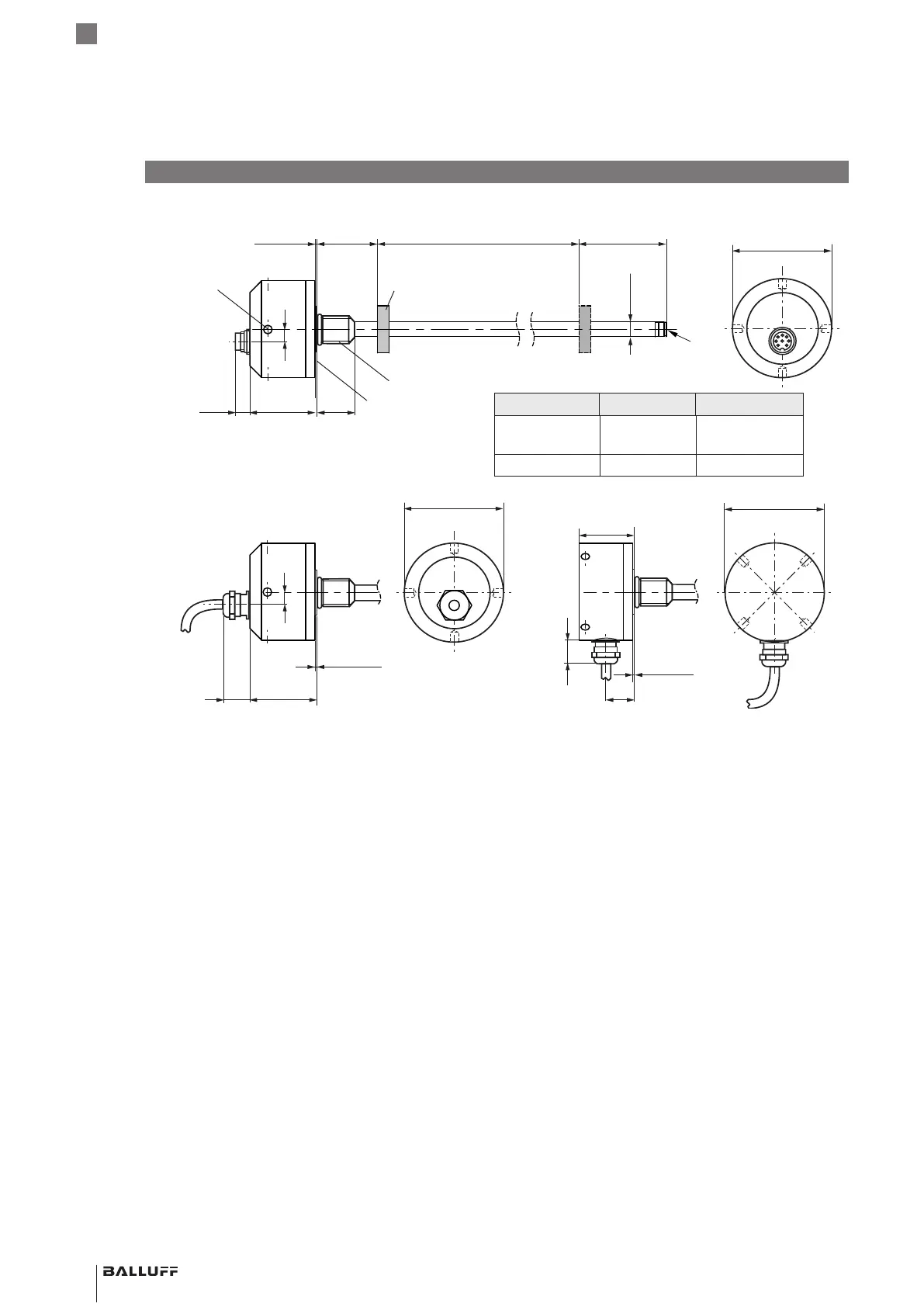
Fig. 3-1:
Ø 65
43
25~12
21
35
60
Ø D1
G
10
0.5 Ø 25
Ø 65
Ø 65
~20
10
0.5 Ø 25
0.5 Ø 25
~20
43
BTL5-…-H/W(8)-…, construction and function
Nominal length: Defines the available measuring range.
Rods with various nominal stroke lengths from 25mm to
5500mm are available depending on the version of the
BTL:
– Ø 10.2mm: Nominal length from 25mm to 5500mm
– Ø8mm: Nominal length from 25mm to 1016mm
Damping zone: Area at the end of the rod that cannot be
used for measurements, but which may be passed over.
3
Construction and function
Version D1 G
…-H/W-… 10.2mm Thread
M4x4/6deep
…-H8/W8-… 8 mm No thread
Ø 5 for hook spanner Ø 65,
max. tightening torque
100Nm
Thread
H: M18×1.5
W: 3/4”-16UNF
H: 40 -1mm
W: 2"-0.04"
Mounting surface
Damping zone
1)
BTL5…-KA _ _ BTL5…-K_ _
BTL5…-S32
Magnet
2)
1)
1)
Unusable area
2)
Not included in scope of delivery
Nominal length =
Measuring range
3.1 Construction
Electrical connection: The electrical connection is made
via a cable or a connector (see Type code on page17).
Housing: Housing containing the processing electronics.
Mounting thread: We recommend assembling the BTL
on the mounting thread:
– BTL5-…-H: M18×1.5
– BTL5-…-W: 3/4”-16UNF
The BTLs with Ø 10.2mm have an additional thread at the
end of the rod to support larger nominal lengths.
Magnet: Defines the position to be measured on the
waveguide. Magnets are available in various models and
must be ordered separately (see Accessories on
page15).
BTL5-P/I/L/M1-M ____ -H/W(8) -S32/KA __ /K __
Magnetostrictive Linear Position Sensor – Rod Style
 Loading...