10 english
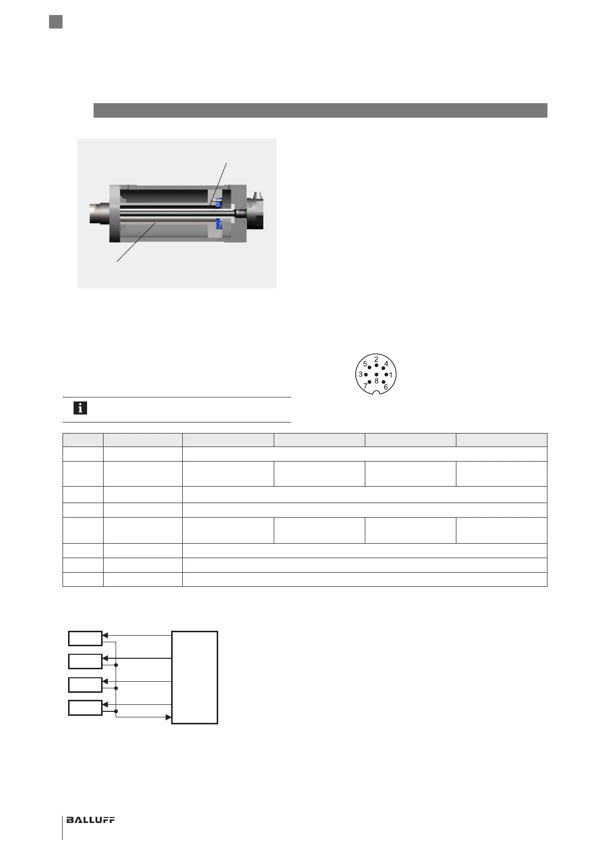
Fig. 4-8:
Magnet
(e.g. BTL-P-1028-15R)
Supporting rod made of non-magnetizable material
Example 2, BTL installed with supporting rod
4.4 Electrical Connection
Depending on the model, the electrical connection is made
using a cable or a connector.
The connection or pin assignments for the respective
version can be found in Tab. 4-2.
Note the information on shielding and cable
routing on page11.
Pin Wire color -P… -I… -L… -M…
1 YE Yellow +Init
2 GY Gray +Start/Stop
(2ndedge)
+Start/Stop
(tri-state, 2ndedge)
+Tor +Start/Stop
(1stedge)
3 PK Pink −Init
4 RD Red Not used
1)
5 GN Green
−Start/Stop
(2ndedge)
−Start/Stop
(tri-state, 2ndedge)
−Tor −Start/Stop
(1stedge)
6 BU Blue GND
7 BN Brown 20…28V
8 WH White Not used
1)
1) Unassigned leads that are not used can be connected to the GND on the controller side but not to the shield.
Tab. 4-2: Connection assignment
No.1
No.2
No.3
No.4
BTL5-I…
Output signal
Start/Stop
Init pulse
Init pulse
Init pulse
Init pulse
Processor or
controller
Fig. 4-9: Connection scheme, bus operation
4
Installation and connection (continued)
Fig. 4-10: Pin assignment of S32 (view from above on BTL),
8-pin M16 circular plug
BTL5-P/I/L/M1-M ____ -H/W(8) -S32/KA __ /K __
Magnetostrictive Linear Position Sensor – Rod Style
 Loading...