www.balluff.com 7english
3
Construction and function (continued)
3.2 Function
The BTL contains the waveguide which is protected by an
outer stainless steel tube (rod). A magnet is moved along
the waveguide. This magnet is connected to the system
part whose position is to be determined.
The magnet defines the position to be measured on the
waveguide.
An externally generated INIT pulse interacts with the
magnetic field of the magnet to generate a torsional wave
in the waveguide which propagates at ultrasonic velocity.
The component of the torsional wave which arrives at the
end of the waveguide is absorbed in the damping zone to
prevent reflection. The component of the torsional wave
which arrives at the beginning of the waveguide is
converted by a coil into an electrical signal. The
propagation time of the wave is used to determine the
position, which is presented on the output in various digital
formats.
Fig. 3-2:
BTL5-P1…
Start Stop
BTL5-I1…
Start Stop
BTL5-L1…
Tor
BTL5-M1…
Start Stop
Digital output signals
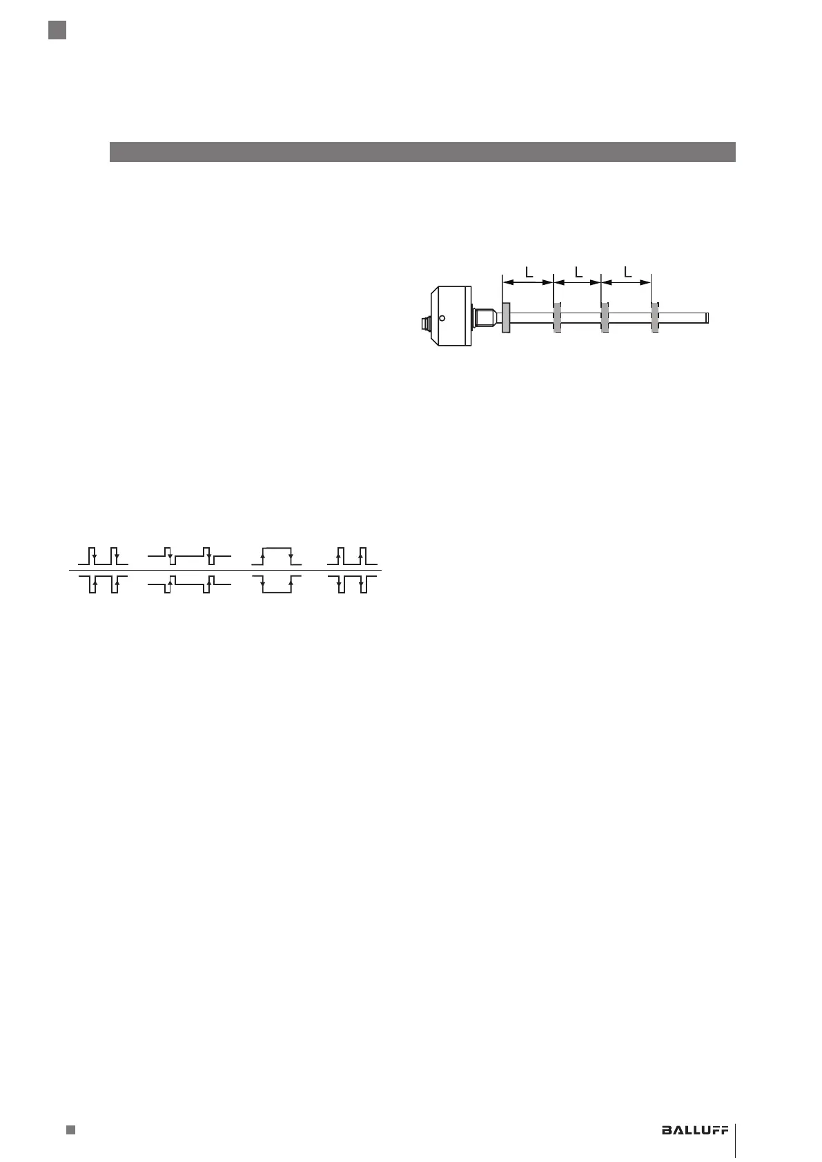
3.3 Number of magnets
Up to 16magnets can be used. The distance (L) between
the magnets must be at least 65mm.
Fig. 3-3: Distance between the magnets
BTL5-P/I/L/M1-M ____ -H/W(8) -S32/KA __ /K __
Magnetostrictive Linear Position Sensor – Rod Style
 Loading...