8 english
4
Installation and connection
4.1 Installation guidelines
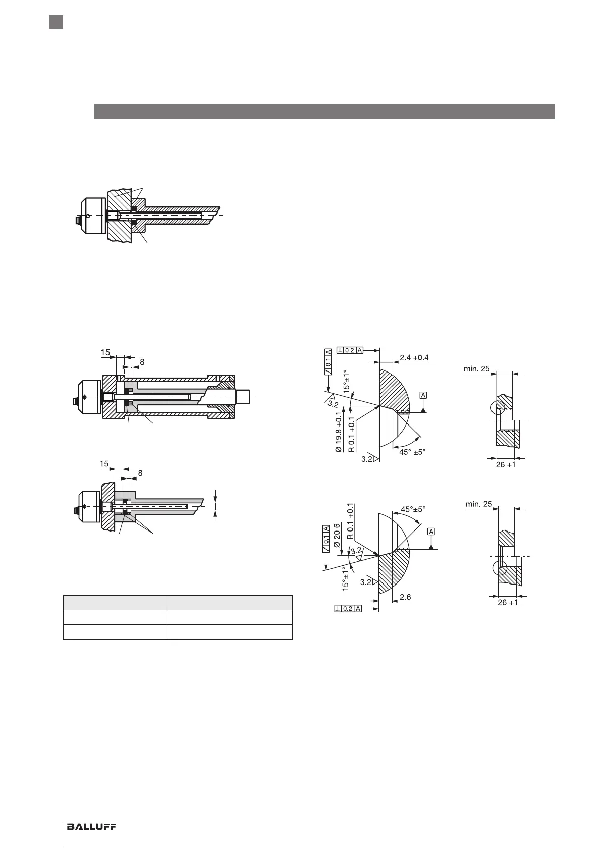
Non-magnetizable material
Fig. 4-1:
Magnet
Non-magnetizable material
Installation in non-magnetizable material
Magnetizable material
If using magnetizable material, the BTL must be protected
against magnetic interference through suitable measures
(e.g. spacer ring made of non-magnetizable material, a
suitable distance from strong external magnetic fields).
Spacer ring made of non-magnetizable
material
Magnet
min. Ø D2
1)
Spacer ring made of non-magnetizable
material
Magnet
1)
min.ØD2=Minimum bore diameter (seeTab. 4-1)
Fig. 4-2: Installation in magnetizable material
Rod diameter Bore diameter
10.2mm At least 13mm
8mm At least 11mm
Tab. 4-1: Bore diameter if installed in a hydraulic cylinder
4.2 Preparing for installation
Installation note: We recommend using non-
magnetizable material to mount the BTL and magnet.
Horizontal assembly: For horizontal assembly with
nominal lengths > 500 mm, support the rod and tighten it
at the end if necessary (only possible with a diameter of
10.2mm).
Hydraulic cylinder: If installed in a hydraulic cylinder,
ensure that the minimum value for the bore diameter of the
support piston is complied with (seeTab. 4-1).
Mounting threads: The BTL comes with an M18×1.5
(according to ISO) or a 3/4"-16 UNF (according to SAE)
thread to secure it. Depending on the version, a mounting
hole must be made before assembly.
Fig. 4-3: Mounting hole M18x1.5 per ISO6149 O-ring15.4x2.1
Fig. 4-4:
Mounting hole 3/4"-16UNF per SAE J475 O-Ring15.3x2.4
Magnet: Various magnets are available for the BTL (see
Accessories on page15).
BTL5-P/I/L/M1-M ____ -H/W(8) -S32/KA __ /K __
Magnetostrictive Linear Position Sensor – Rod Style
 Loading...