www.balluff.com 17français
8
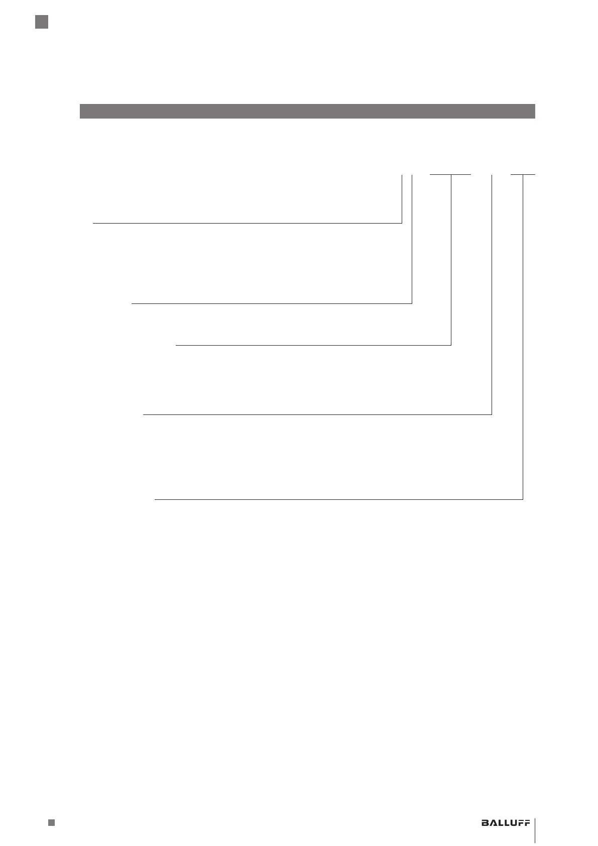
Code de type
BTL5 - P1 - M0500 - H - S32
Interface:
P = Start/Stop, 2e front actif
I = Start/Stop, tri-state, 2e front actif
L = Tor
M = Start/Stop, 1e front actif
Tension de service:
1 = 20…28VCC
Longueur nominale (4chiffres):
M0500 = indication métrique en mm, longueur nominale 500mm
(H8/W8: M0025…M1016)
(H/W: M0025…M5500)
Version à tige, fixation:
H= filetage de fixation métrique M18×1.5, joint torique, diamètre de tige 10,2mm
W = filetage en pouce 3/4"-16UNF, joint torique, diamètre de tige 10,2mm
H8= filetage de fixation métrique M18×1.5, joint torique, diamètre de tige 8mm
W8= filetage en pouce 3/4"-16UNF, joint torique, diamètre de tige 8mm
Raccordement électrique:
S32 = 8pôles, connecteur M16 selon CEI130-9
KA05 = câble 5m, axial (PUR)
K05 = câble 5m, radial (PUR)
BTL5-P/I/L/M1-M ____ -H/W(8) -S32/KA __ /K __
Système de mesure de position magnétostrictif – modèle à tige
 Loading...