www.balluff.com 11english
4
Installation and connection (continued)
4.5 Electrical Connection
The BTL is attached via connectors.
Note the information on shielding and cable
routing on page10.
4.5.1 Connecting the supply voltage, control and
data signals
The connection assignments are shown in Fig. 4-9,
Tab. 4-4 and Tab. 4-5.
Fig. 4-9:
1
1
3
5
2
3
4
4
1
5
2
3
4
Bus Out
Bus In
Power
BKS pin assignment, BTL…-S103 connector, view on the
plug/socket side of the BTL
(pin)
(socket) (pin)
Pin
Control and data signals
BUS IN BUS OUT
1 VP +5V (output)
2 RxD / TxD-N (A)
3 Data GND
4 RxD / TxD-P (B)
5 Shield
Tab. 4-4: Control and data signals connection assignment
Pin
Supply voltage (external)
Power
1 +24V
3 0V (GND)
4 Shield
Tab. 4-5: Supply voltage connection assignment
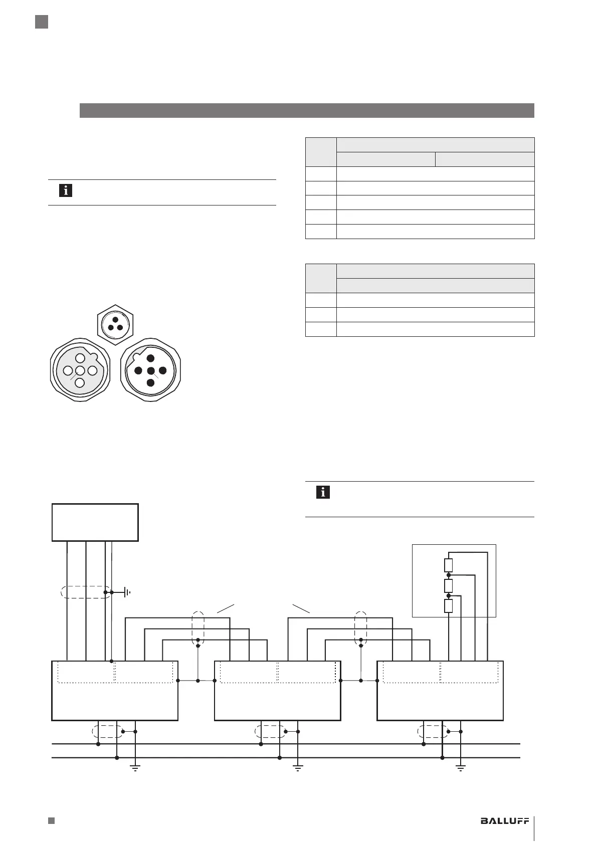
4.5.2 Connection example
Fig. 4-10:
A B
PROFIBUS-DP
Master
390 Ω
390 Ω
220 Ω
+24 V
0 V
# 1
# 0
# n
# 125
3
4
44
22
BTL5-T1…-S103
BKS-S 48-15-CP-…
BKS-S105-R01
PROFIBUS-DP Interface
55
1
Bus In Bus Out
3
4
4
2
PROFIBUS-DP Interface
5
1
Bus In Bus Out
4
2
5
3
4
2
4
PROFIBUS-DP Interface
3
1
Bus In Bus Out
4
2
5
1
BTL5-T1…-S103 BTL5-T1…-S103
BTL5-T1…-S103 with master, connection example
BKS-S103/GS103-CP-…
Bus connector
BKS-S105-R01
required for IP67!
In this version the connections for power
supply, Bus In and Bus Out are located on
separate connectors.
BTL5-T1 __ -M ____ -P-S103
Magnetostrictive Linear Position Sensor – Profile Style
 Loading...