www.balluff.com 9english
4
Installation and connection (continued)
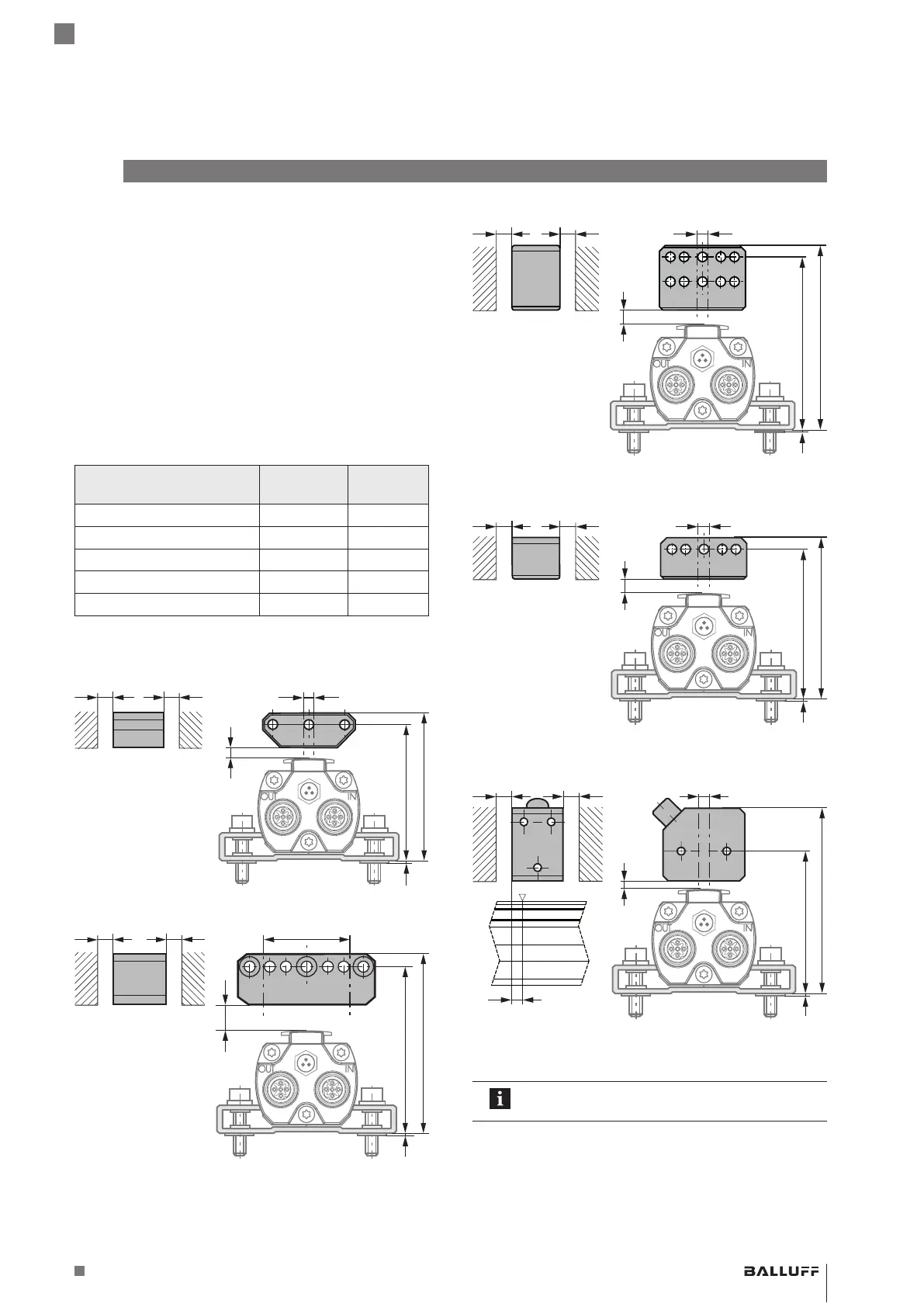
4.3 Floating magnets
Note when installing the magnet:
– To ensure the accuracy of the linear position sensor,
the magnet is attached to the moving member of the
machine using non-magnetizable screws (stainless
steel, brass, aluminum).
– The moving member must guide the magnet on a
parallel line to the BTL.
– Distance A between the magnet and parts made of
magnetizable material must be kept to at least 10 mm
(see Fig. 4-4 to Fig. 4-8).
– For distance B between the magnet and the BTL and
for the center offset C (see Fig. 4-4 to Fig. 4-8) the
following values must be maintained:
Magnet type Distance
B
1)
Offset C
BTL5-P-3800-2 0.1…4mm ±2mm
BTL5-P-5500-2 5…15mm ±15mm
BTL5-P-4500-1 0.1…2mm ±2mm
BTL6-A-3800-2 4…8mm
2)
±5mm
BTL6-A-3801-2 4…8mm
2)
±5mm
1)
The selected distance must remain constant over the entire stroke length.
2)
For optimal measuring results a distance B of 6…8mm is recommended.
Tab. 4-2: Distance and offset for floating magnets
Fig. 4-4:
B
50+4
A
A
55+4
1
Dimensions and spacing with magnet BTL5-P-3800-2
Fig. 4-5:
B
1
61+10
66+10
Dimensions and spacing with magnet BTL5-P-5500-2
Fig. 4-6:
B
1
74+4
69+4
Dimensions and spacing with magnet BTL6-A-3800-2
Fig. 4-7:
B
A
A
1
63+4
58+4
Dimensions and spacing with magnet BTL6-A-3801-2
Fig. 4-8:
B
A
A
4
1
81+2
57.5+2
Dimensions and spacing with BTL5-P-4500-1 electroma-
gnet (24V/100mA)
The measuring range is offset by 4mm towards
the BTL plug (see Fig. 4-8).
BTL5-T1 __ -M ____ -P-S103
Magnetostrictive Linear Position Sensor – Profile Style
 Loading...