12 english
5
Installation and connection (continued)
5.4 Electrical connection
Depending on the model, the electrical connection is made
using a cable or a connector. The connection or pin
assignments for the respective version can be found in
Tab. 5-2 to Tab. 5-5.
See the information about Shielding and cable
routing on page 13.
5.4.1 Connectors
S15 connector
Fig. 5-9: Pin assignment ofS15 (view from above on BTL)
Pin Signal
1 0V (output2)
2 0V (output1)
3 Output2
4 C/Q
5 Output1
6 GND
1)
7 10…30V
8 Not used
)2
1)
Reference potential for supply voltage and EMC-GND.
2)
Unassigned leads that are not used can be connected to the GND on
the controller side but not to the shield.
Tab. 5-2: Pin assignmentS15
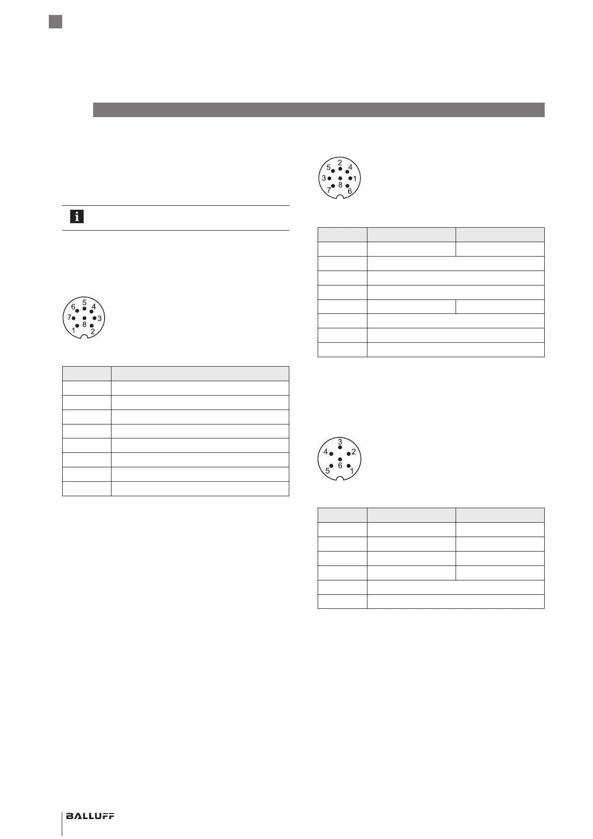
S32 connector
Fig. 5-10: Pin assignment ofS32 (view from above on BTL)
Pin C15AA/A1… C15AE/A5/AC…
1 Not assigned
1)
Output1
2 0V
3 Output2
4 C/Q
5 Output1 Not assigned
1)
6 GND
2)
7 10…30V
8 Not assigned
1)
1)
Unassigned leads that are not used can be connected to the GND on
the controller side but not to the shield.
2)
Reference potential for supply voltage and EMC-GND.
Tab. 5-3: Pin assignmentS32
S35 connector
Fig. 5-11: Pin assignment ofS35 (view from above on BTL)
Pin C15AA/A1… C15AE/A5/AC5…
1 Output1 Output1
2 0V (output1) 0V
3 Output2 Not assigned
1)
4 0V (output2) Not assigned
1)
5 10…30V
6 GND
2)
1)
Unassigned leads that are not used can be connected to the GND on
the controller side but not to the shield.
2)
Reference potential for supply voltage and EMC-GND.
Tab. 5-4: Pin assignmentS35
BTL PF _ 400- _ _ _ _ -C15A _ _ _ _ - _ _ _ _ _ _
Magnetostrictive Linear Position Sensor – Profile Style
 Loading...


