www.balluff.com 13english
5
Installation and connection (continued)
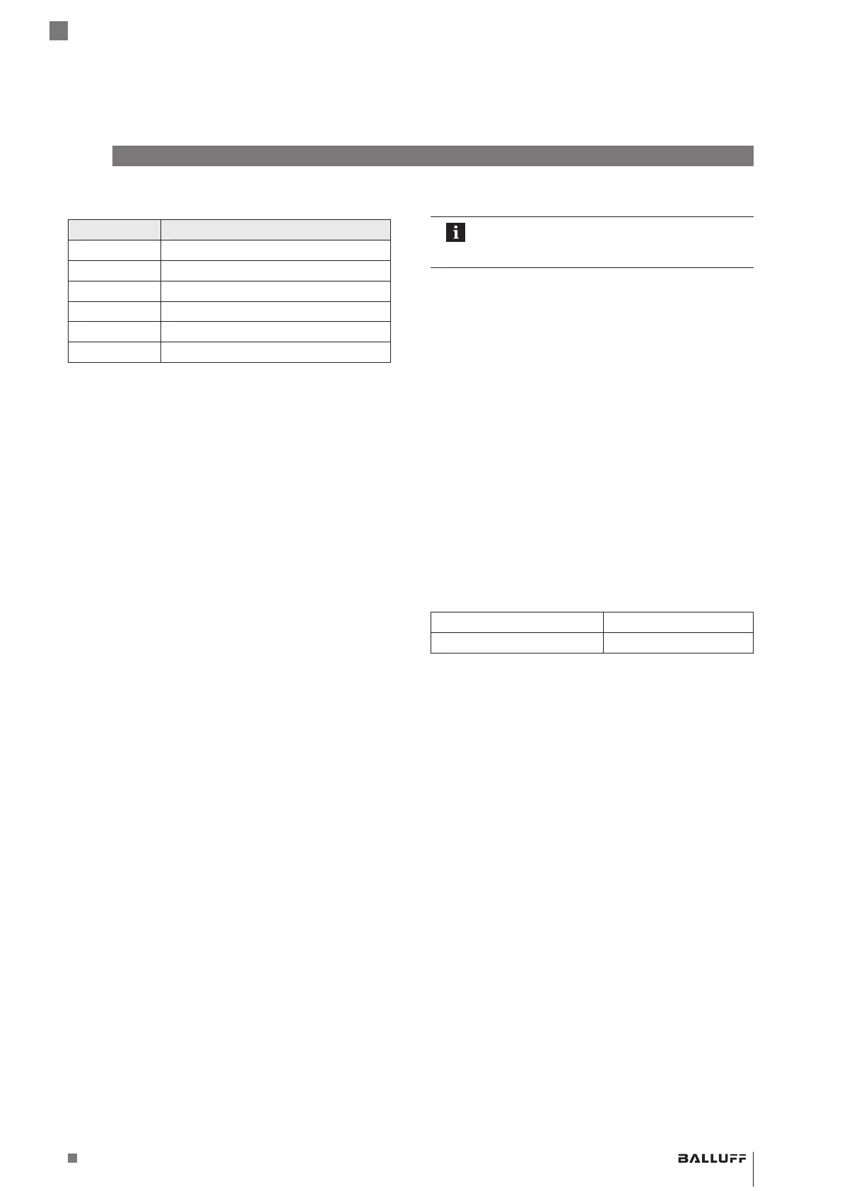
5.4.2 Cable connection
Color Signal
GY gray 0V
PK pink Output2
WH white C/Q
GN green Output1
BU blue GND
1)
BN brown 10…30V
1)
Unassigned leads that are not used can be connected to the GND on
the controller side but not to the shield.
Tab. 5-5: Connection assignment, cable
5.5 Shielding and cable routing
Defined ground!
The BTL and the control cabinet must be at the
same ground potential.
Shielding
Observe the following instructions to ensure
electromagnetic compatibility (EMC):
– Connect BTL and controller using a shielded cable.
Shielding: Braided copper shield with minimum 85%
coverage.
– Shield is internally connected to connector housing.
Magnetic fields
The position measuring system is a magnetostrictive
system. Be sure to provide sufficient distance of the BTL
from strong external magnetic fields.
Cable routing
All cables between BTL, control and power supply must
be routed tension-free. In order to avoid electromagnetic
interference, ensure sufficient distance to cables carrying a
heavy current and cables with high-frequency voltage
signals (e.g. of frequency converters).
Cable length
BTL …-C15AA/A1… Max. 30 m
1)
BTL …-C15AE/A5/AC/A3… Max. 100 m
1)
1)
Prerequisite: Construction, shielding and routing preclude the effect of
any external noise fields.
Tab. 5-6: BTL cable lengths
BTL PF _ 400- _ _ _ _ -C15A _ _ _ _ - _ _ _ _ _ _
Magnetostrictive Linear Position Sensor – Profile Style

 Loading...


