www.balluff.com 15english
6
Startup and operation (continued)
6.2 Operation
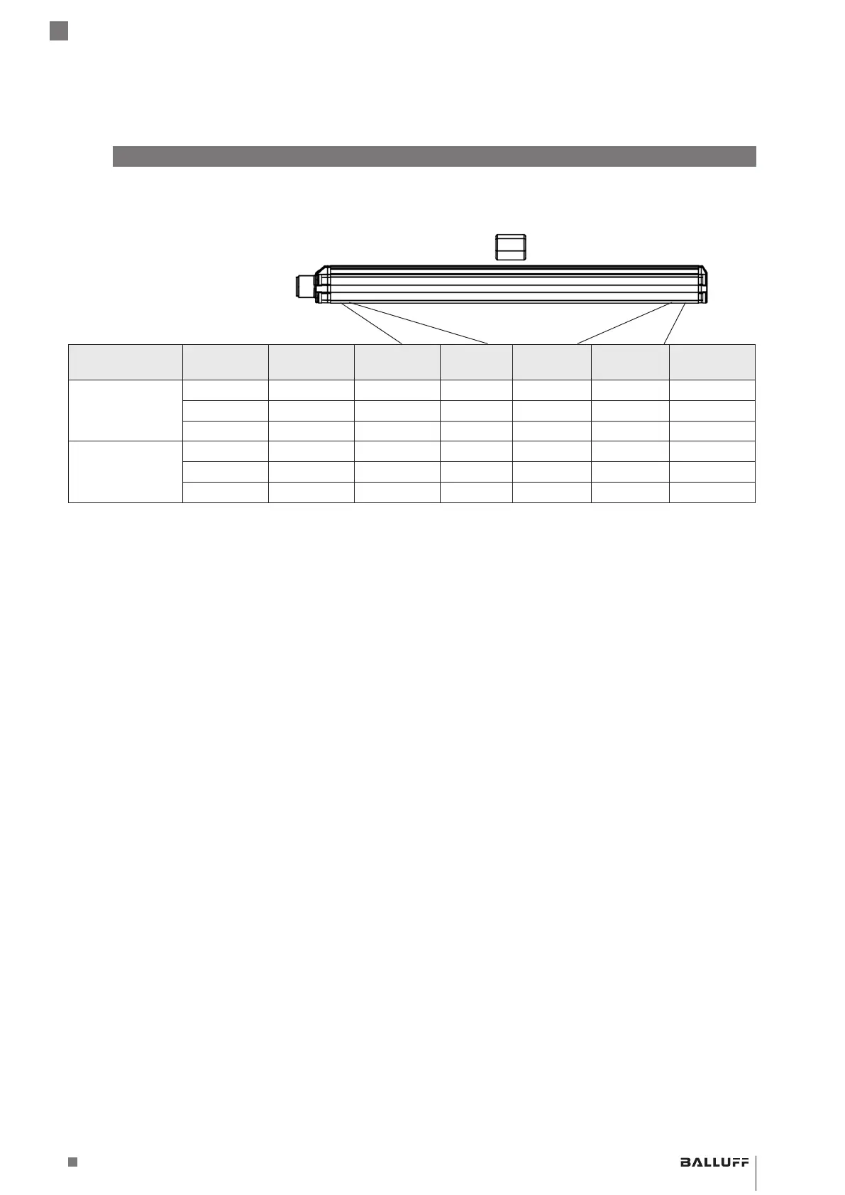
Null point End point
Characteristic
curve
BTL Unit Minimum
value
Null value End value Maximum
value
Error value
Rising …-C15AA… V −0.4 0 10.0 10.4 10.5
…-C15AE… mA 3.6 4.0 20.0 20.4 1.8
…-C15AC… mA −0.4 0 20.0 20.4 21.0
Falling …-C15A1… V 10.4 10.0 0 −0.4 10.5
…-C15A5… mA 20.4 20.0 4.0 3.6 1.8
…-C15A3… mA 20.4 20.0 0 −0.4 21.0
Tab. 6-1: Value table for factory default
6.3 Operating notes
– Some settings can be modified (see Configuration with
the Balluff Engineering Tool (BET) on page16) (does
not apply to BTL PF_400-…S35).
– Regularly check function of the BTL and all associated
components.
– Take the BTL out of operation whenever there is a
malfunction.
– Secure the system against unauthorized use.
– Check fasteners and retighten if needed.
6.4 Maintenance
The product is maintenance-free.
BTL PF _ 400- _ _ _ _ -C15A _ _ _ _ - _ _ _ _ _ _
Magnetostrictive Linear Position Sensor – Profile Style

 Loading...


