C
ISTRUZIONI DI MONTAGGIO E USO
INSTALLATION AND USE
12
um_boxtron e14_it-en_rev. 1.0
1
2
3
4
ON
1
2
3
4
ON
1
2
3
4
ON
1
2
3
4
ON
1
2
3
4
ON
1
2
3
4
ON
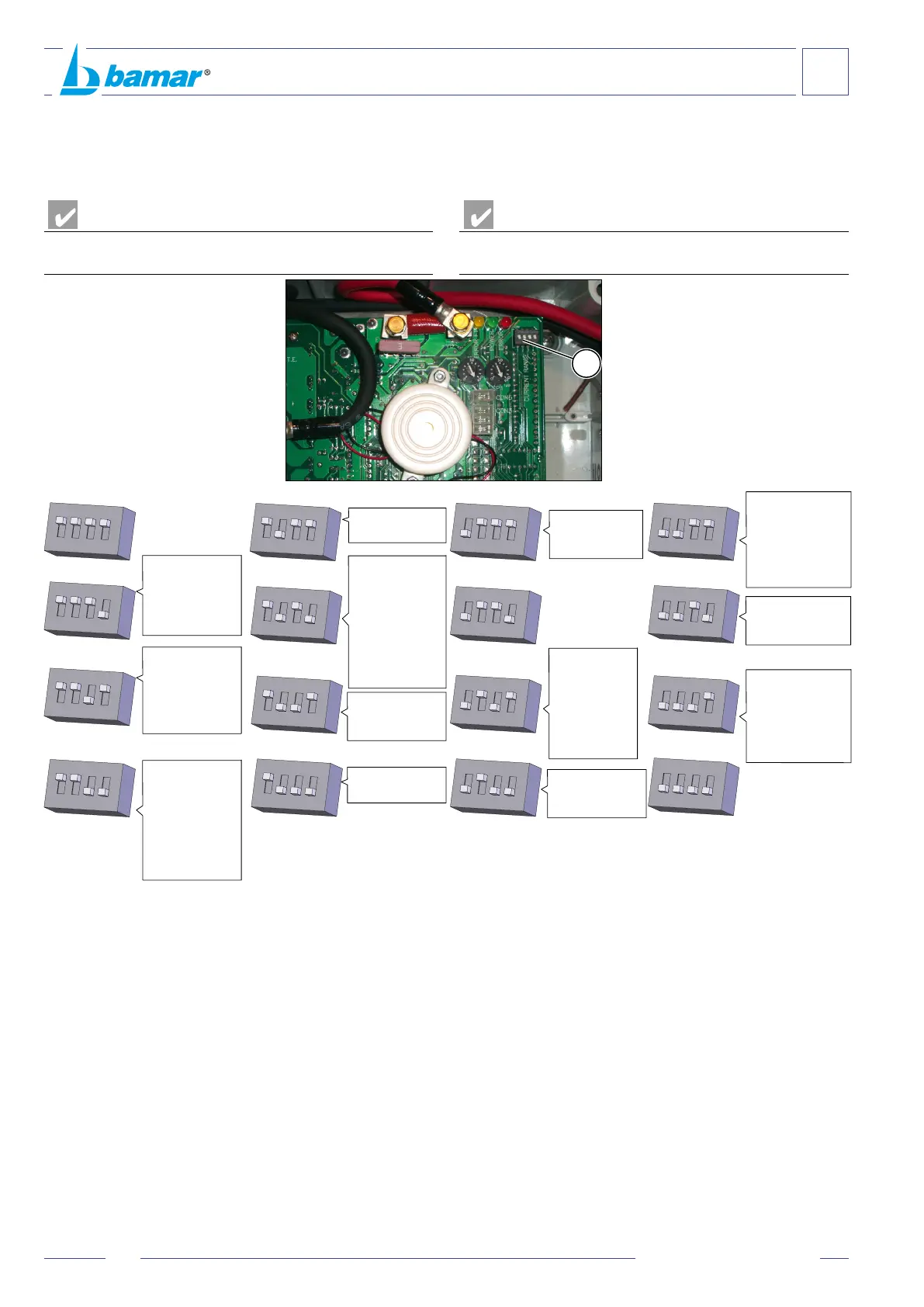
C-8 TABELLA PER LA SELEZIONE DELLE
SOGLIE DI INTERVENTO DI MASSIMA
CORRENTE “CURRENT RANGE” AMPÈRE (A)
PERICOLO
PERICOLO DI FOLGORAZIONE
ATTENZIONE
AVVERTENZA
Tabella valida per BOXTRON
®
E14 con numero seriale di identicazione
dal N° 0000E e successivi.
C-8 DIAGRAM FOR THE SELECTION OF THE
MAXIMUM CURRENT INTERVENTION
THRESHOLD-AMPÈRE (A) “CURRENT RANGE”
DANGER
DANGER OF ELECTROCUTION
CAUTION
WARNING
Diagram suitable for BOXTRON
®
E14 with identication number from
0000E and above.
1
2
3
4
ON
1
2
3
4
ON
1
2
3
4
ON
1
2
3
4
ON
1
2
3
4
ON
1
2
3
4
ON
1
2
3
4
ON
1
2
3
4
ON
1
2
3
4
ON
1
2
3
4
ON
90 A
150 A
C-9 SIGNIFICATO SEGNALAZIONE LED
• LED GIALLO (Y):
Il LED giallo spento indica che il fusibile conduce. Il LED giallo acceso
indica che il fusibile F1 è interrotto e quindi manca alimentazione al
BOXTRON
®
E14.
Se il LED giallo è acceso il fusibile F1 deve essere sostituito con altro
fusibile di corretto amperaggio.
L’interruzione di questo fusibile non spegne il LED verde (G).
• LED VERDE (G):
Il LED verde acceso indica la corretta alimentazione elettrica del
BOXTRON
®
E14.
Il LED verde spento indica la mancata alimentazione elettrica al
BOXTRON
®
E14.
• LED ROSSO (R):
Il LED rosso spento indica che non sono segnalati errori oppure il
BOXTRON
®
E14 è spento.
Il LED rosso acceso a luce ssa, indica che il BOXTRON
®
E14 sta
lavorando regolarmente (motore in azione).
Il LED rosso che lampeggia rapidamente indica uno stato di anomalia
o errore.
C-9 DESCRIPTION OF LED SIGNALS
• YELLOW LED (Y):
If the yellow LED is o, it shows the fuse conducts. If it is on, it shows
the F1 fuse is interrupted, therefore the BOXTRON
®
E14 is powerless.
If the yellow LED is on, the F1 fuse should be replaced with another
one having the right amperage.
The interruption of this fuse does not turn o the green LED (G).
• GREEN LED (G):
If the green LED is on, it shows a correct electric supply to the
BOXTRON
®
E14.
If the green LED is o, it shows a lack of electric supply to the
BOXTRON
®
E14.
• RED LED (R):
If the red LED is o, it either shows no errors occurred, or the
BOXTRON
®
E14 is turned o.
If the red LED is on, with xed light, it shows the BOXTRON
®
E14 is
working (motor in action).
If the red LED is rapidly ashing is shows that an error or anomaly
occurred.
A
15 A
RGEEL 80/24V
RGIEL 80/24V
RRGEEL 80/24V
RRGIEL 80/24V
10 A
20 A
RGEEL 80/12V
RGIEL 80/12V
RRGEEL 80/12V
RRGIEL 80/12V
BWSE 5t 24V
30 A
BFBME 110 24V
BFBME 110 48V
BFBME 140 24V
RGEEL 110/24V
RGIEL 110/24V
RRGEEL 110/24V
RRGIEL 110/24V
50 A
BFBME 110 12V
BFBME 140 12V
EJF 1 24V
MEJ 1 24V
RGEL 65 24V
TBEL 65 24V
RLG-CODE SE WL5T
CODE PE 8-10T
140 A
MEJ 2 24V
RGEEL 160 24V
RRGEEL 160 24V
MEJ 3 24V
EJF 3 24V
100 A
EJF 1 12V
EJF 2 24V
MEJ 1 12V
RGEL 65 12V
TBEL 65 12V
GFSE 8 24V
80 A
GFSE 12 24V
40 A
BWSE 5t 12V
110 A
BFBME 182 24V
60 A
RGIEL 110/12V
RRGIEL 110/12V
70 A
BWSE 8-10T 24V
130 A
GFSE 16 24V
120 A
RGEEL 130 24V
RRGEEL 130 24V
RGEL 95 24V
TBEL 95 24V
GFSE 8 12V