6 - 8 Fiveways Boulevard, Keysborough, VIC, Australia 3173
P: 1300 133 944 E: sales@automatictechnology.com.au
W: www.automatictechnology.com.au
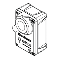
Wiring the Base Station to the Opener
a. Power off Opener.
b. Connect the Wireless WPE-1v1 Base Station to the opener / console as per
wiring diagram below.
NOTE: Multiple Sets of Wireless WPE-1v1 can be connected to certain openers
and the C02L Console. Gather the set of black wires together and insert into the
same terminal as per above wiring diagram. The same process applies to the red
wires. The yellow wires are individually inserted into to EB1 and EB2 (openers) or
SB1, SB2 and SB3 (C02L Console)
Wireless Kit WPE-1v1
Refer to compatibility table (page 2) for Product compatibility.
0V V+ EB1 OR EB2 (OPENERS)
COM V+ IN2 (C01L - CONSOLES)
0V V+ SB1, SB2 OR SB3 (C02L - CONSOLES & GATES)
Receiver
+
+
RESET
RESET
LED
LED
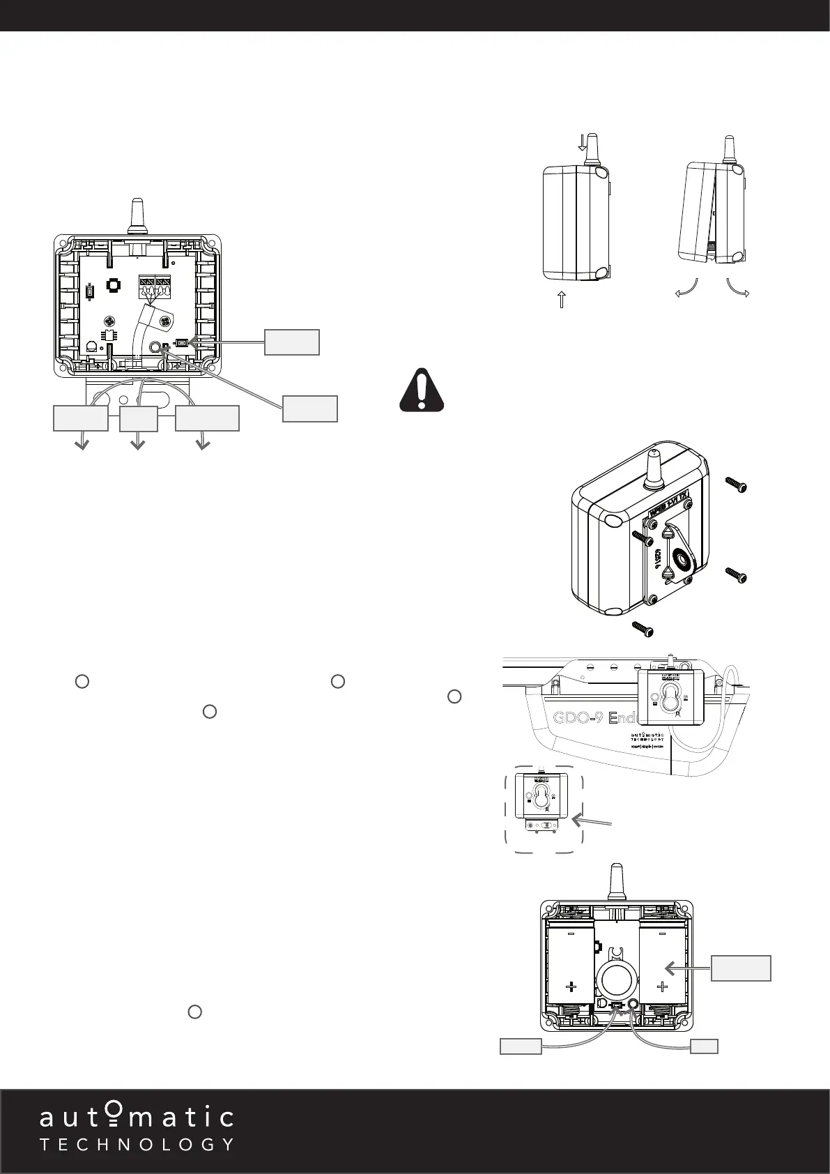
Base Station on the wall
Apply pressure here
Pull covers apart
Fixing the Base Station to Wall/Opener
The base station can be fixed to the wall using the two (2) 6.9 x 25 plastic wall
plugs
9
and two (2) M6 x 25 self tapping screws
10
. It can also be attached
directly to a sectional opener using the M6 x 16 Hex serration head screw
13
and
M6 Hex serration flange nut
12
. The wire can be fed through the top gromet of
the opener.
NOTE: The bracket may also be rotated so the base station hangs above the
power head.
Inserting batteries into receiver and transmitter
a. Insert two (2) C-Type batteries in the Receiver (WPB-4.02 RX) by removing
the front cover.
b. The LED on the receiver will light up and after the communication is established
between the receiver and base station the LED on the base station and the
receiver will turn off. This can take up to 60secs.
c. Repeat step (a) to insert batteries into the Transmitter (WPB-4.02 TX).
d. The LED on the transmitter will light up and after communication is established
between the transmitter and base station the LED on the transmitter and on
the receiver will start to flash.
e. The flashing indicates the link is established between the transmitter and base
station, receiver and base station, but receiver and transmitter are not yet
alligned.
f. Put cover back on Transmitter and Receiver and secure with eight (8)
M6 x 25 screws (black)
11
.
RED
YELLOW
BLACK
BATTERY
WARNING! When using the C01L Console ensure that the
“PE Beam Type” (Menu 6.4) is set to “2-wire” mode
before setting limits.
 Loading...