B&D Doors is a division of B&D Australia Pty Ltd
P: 13 62 63
W: www.bnd.com.au
WARNING! When using PE Beams, the
doorway must be clear of all obstructions
and persons at all times. The location
of the beams and manner in which it is
installed might not give safety protection
at all times. Check to make sure that the
height of the beam and type used give
maximum protection possible.
WARNING! PE beams must be installed
if the closing force at the bottom edge
of the door exceeds 400N (40kg force)
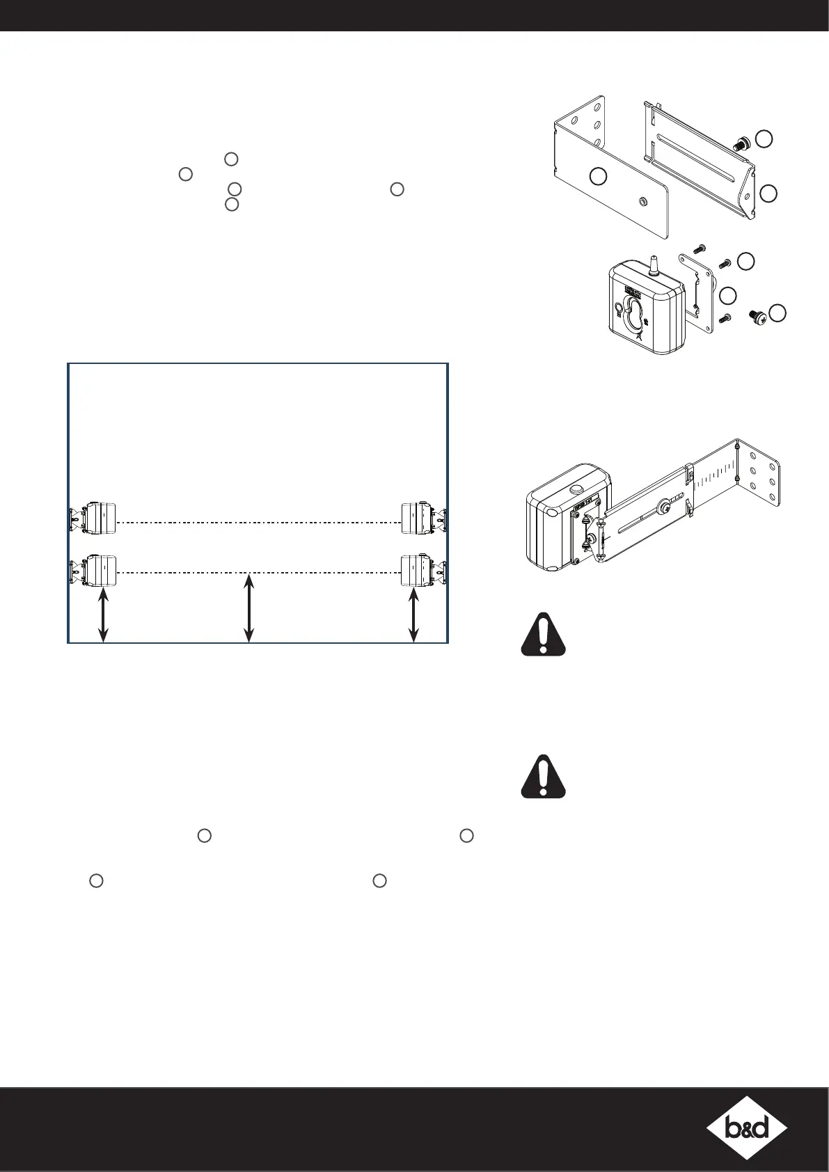
Assembling the Mounting Bracket
a. Attach the PE 2000TS Bracket
1
to the Receiver (WPB-4.02 RX) using four (4)
M3 x 5 Taptite screws
4
.
b. Connect the mounting bracket
3
to the adjustment bracket
2
with two (2) of
the M5 x 10 Pan Head Screws
5
.
c. Repeat steps (a) and (b) to assemble the Safety Beam Transmitter
(WPB-4.02TX).
d. Mount the receiver on the side of the doorway / gateway closest to the opener
/ console and the transmitter on the other side in line with the receiver. The
mounting surface should be rigid. Affix with a minimum of four (4) screws
(not supplied).
NOTE: When using two (2) sets of Safety Beams within the opening you must
alternative the configuration. See diagram below.
e. ATA recommends the transmitter and receiver are placed in line of sight,
with the beam 100mm above the ground level (as per AS60335). This can be
achieved by ensuring the bottom of the receiver and transmitter are 65mm
above ground level. They should also be placed as close as possible to the
door / gate opening.In industrial applications it is recommended that multiple
Safety Beams are fitted.
Assemble Flush Mounting Kit (for minimum sideroom applications)
For applications which have limited space available or certain environmental
factors a flush mounting kit can be used.
a. Attached the transmitter (WPB-4.02TX) and receiver (WPB-4.02RX) to the
two (2) PEB4-W1 Bracket
5
with the eight (8) M3 x 8 Taptite screws “P”
6
.
b. Ensure to take note of the ATA recommendation in step (e) above and fix the
TX and RX to the wall or rigid surface using the two (2) 6.9 x 25 plastic wall
plugs
8
(if wall) and two (2) M6 x 25 self tapping screws
7
.
Aligning the Transmitter and Receiver
a. Make horizontal and/or vertical adjustment on the transmitter until the red
LED on the receiver stays on, this indicates alignment.
b. Make horizontal and/or vertical adjustment on the receiver until the red LED
on the transmitter stays on, this indicates alignment.
Setting the limits
After aligning the safety beams, refer to the openers manual to set the travel
limits. If opener has been installed previously, ensure you clear the limits and
follows instructions to set limits again.
4
1
5
2
3
5
Right side
bracket
TX - 1RX - 1
TX - 2
RX - 2
65mm
Floor Level
100mm
65mm
Right side
bracket
assembled
Wireless Kit WPE-1v1
Continued . . .
NOTE: Mount the receiver on the side of
the doorway / gateway closest to the base
station.
 Loading...