Do you have a question about the B&G HB-1000I and is the answer not in the manual?
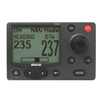
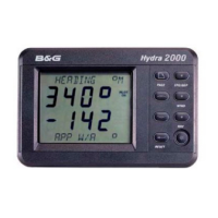
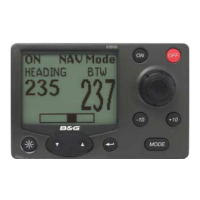
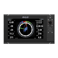
The h1000 pilot display head controls the autopilot and integrates with other h1000 instruments.
Procedure for cutting a panel hole and securely mounting the pilot display unit using its bracket.
The h1000 compass is an electronic fluxgate for use with all h1000 systems, housed in a sealed casing.
The RRU provides rudder position information to the pilot computer unit via a sealed, high-specification potentiometer.
Details on hydraulic pump driven systems for boats without existing hydraulic steering, available in three sizes.
Description of the reversible hydraulic drive pump, its function, and service ports.
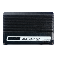
The ACP Unit houses autopilot electronics and controls rudder drive options, designed for vertical mounting.
How to select clutch/solenoid voltages using dip-switches on the ACP computer drive PCB.
Diagrams illustrating connections for alarms, optional controls, drives, pumps, and sensors.
Waterproof remote controller with six function buttons and status LED for palm-of-the-hand autopilot control.
A large, red, waterproof press-switch that initiates the MOB sequence and sounds an alarm.
Joystick for direct rudder control, deck-mountable, connects to the h1000 ACP unit via a 10m cable.
Sets units of measurement, damping, and speed calibration factor for the autopilot.
A checklist to ensure system correctness before applying power and starting autopilot calibration.
Procedures performed at the dockside before sea trial, covering essential system settings and checks.
Choose the boat type (Sail, Power disp., Power planing) to optimize autopilot steering response.
Define the full travel limits of the rudder by setting port and starboard end stops.
Parameters set and checked during the initial sea trial, including Rudder amidships, Boat lag, and Rudder gain.
Adjust boat lag to manage the time the boat takes to respond to helm changes, correcting for overshoot.
Fine-tune the autopilot's steering performance by adjusting rudder gain for optimal response and course keeping.
Manually adjust rudder gain for optimal steering, balancing response and rudder movement.
Fault: Rudder not calibrated or memory corrupted. Check list provided for diagnosis.
Fault: Rudder reference signal outside calibration limits. Check installation, wiring, and voltage.
Fault: Pilot cannot move rudder or moves it incorrectly. Check power, installation, and dip switches.
Fault: Boat stationary or slow, or speed sensor not working. Check speed input and connections.
Fault: Compass or gyro data lost or unreliable. Check connections to the compass sensor or external devices.
Fault: Pilot overcorrects course, causing an 'S' wake. Check drive system, settings, gain, lag, and compass location.
| Brand | B&G |
|---|---|
| Model | HB-1000I |
| Category | Marine Equipment |
| Language | English |