Do you have a question about the B&G Network Series and is the answer not in the manual?
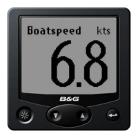
Adjusts the response time of the display to changes in boat speed.
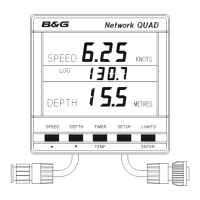
Sets boat speed display units (Knots/MPH) and log units.
Manual boat speed calibration procedure.
Manual log calibration procedure.
Automatic boat speed and log calibration procedure.
Resets the Dead Reckoned Distance log.
Corrects displayed boat speed manually to a known value.
Adjusts log calibration figure (Hz/Knot) for percentage error.
Automatically calibrates boat speed and log for accuracy.
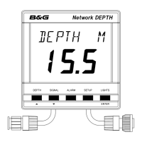
Adjusts the depth datum for reference point.
Sets alarm for when water depth is less than a value.
Sets alarm for when water depth is more than a value.
Sets alarm for when depth is outside two limits.
Factory set and adjustable shallow water alarm settings.
Factory set and adjustable deep water alarm settings.
Factory set shallow/deep limits for anchor alarm.
A reset log for distance, also resets max/average speed.
Displays the Stored Log in Nautical or Statute Miles.
Details three available timers: 10 min, 5 min, and count-up.
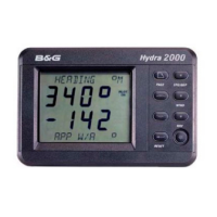
Shows how depth alarms are displayed on other Network units.
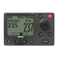
Shows how Pilot alarms are displayed on other Network units.
Describes fault messages from Network Pilot on other units.
Details how to handle internal errors on the Network QUAD unit.
Guidelines for selecting the optimal mounting position for the unit.
Step-by-step instructions for physically mounting the unit.
Details construction, display, dimensions, and weight.
Specifies operating and storage temperature, and humidity limits.
Outlines power supply requirements and current draw.
Describes cable types and connection methods.
Notes internal audible alarm and external control output.
Lists NMEA output sentences for repeater units.
| Manufacturer | B&G |
|---|---|
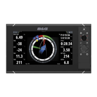
| Radar Support | Yes |
| AIS Support | Yes |
| NMEA 2000 Support | Yes |
| Waterproof Rating | IPX7 |
| Touchscreen | Yes |
| GPS | Yes |