P. 16 - Outputs - Failure output
Output: failure output [OKout]
This is a relay with potential free contacts. They provide a perfect separation between
BANDIT internal electronics and the “outside world”.
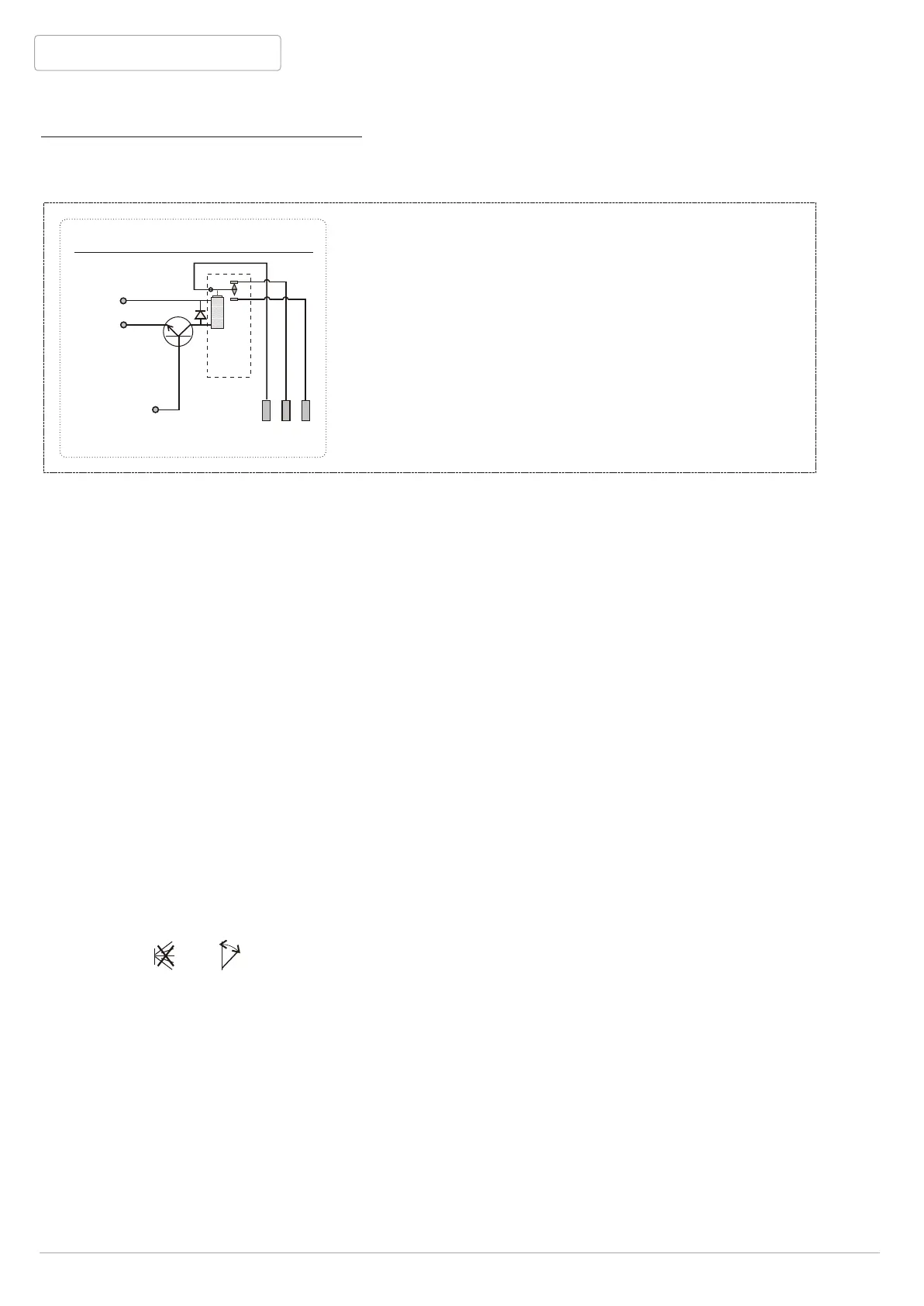
0 V
Com.
N.C.
N.O.
12 V
MCU output
Schematic display of a relay output
[Okout].
Relay
12 V /
1 A
Electrical properties of a relay output:
- potential free
- maximum 1 Amp load with 24 V.
- spark suppressors (varistors or run-free diodes) over
contacts, for switching inductive loads
(relay coils, etc.).
- in case of an internal 12 V supply failure (<8 V.) or
the MCU resets or is being reset, this output
will switch to its rest position(COM and NC closed).
This relay contact is represented by 3 terminal connectors [Okout] on the PCB.
COM is the common contact. COM and NO are closed (relay operated) as long as there is no
internal failure detected through BANDIT internal electronics.
As long as internal failure is detected, the [OKout] contact is in rest (COM and NO open) and
the red [OKout] PCB Led will go on (see PCB layout on page 9).
BANDIT-electronics can detect the following internal failures:
4The glass fuse F2 (500 mA of [Supply1]) is interrupted.
4The glass fuse F3 (6.3 A battery fuse) is interrupted.
4There is no battery present or the battery load is too low.
4The environment temperature of the built-in HY-3 pack is above 50°C.
4The temperature of the heat exchanger is too low to admit a fog expulsion. This can mean:
a) the internal over-temperature fuse is interrupted
b) the heat resistance of the heat exchanger is faulty
4The internal fan isn’t functioning correctly.
4The unit is asking more than 7 days for a replacement of the HY-3 pack. This item is no real
failure but an abnormal situation on which the reliability is endangered due to too less
reserve of fog fluid. See also page 26, replacement of HY-3 pack.
4A lack of presence of mains supply for more than 15 minutes (mains or head fuse F1).
4The MCU is measuring abnormal values through the inputs of its sensors.
4An abnormal condition has remained present for more than 3 hours. This abnormal
condition is indicated through the fast blinking of the “Failure” front led. This is: Red jumper
isn’t plugged in and/or one or both “Control Box” switches are still on active
positions ( or ).
As soon as the internal failure is restored, the failure indication will disappear automatically
and the normal situation will be restored: [OKout] enforced (COM and NO closed) and the red
[OKout] Led on the PCB will go off.
A common application for this useful [OKout] output is to connect this output to a
programmable input of the alarm system or an auto-dialer. This way it’s very simple to report
through phone reports or other means of communication to the control rooms
(PAC's) that there may be BANDIT problems.
BANDIT 240 DB v.206
H
Y
-
3
 Loading...