p. 32 - Examples of application - diagram 3
BANDIT 240 DB v.206
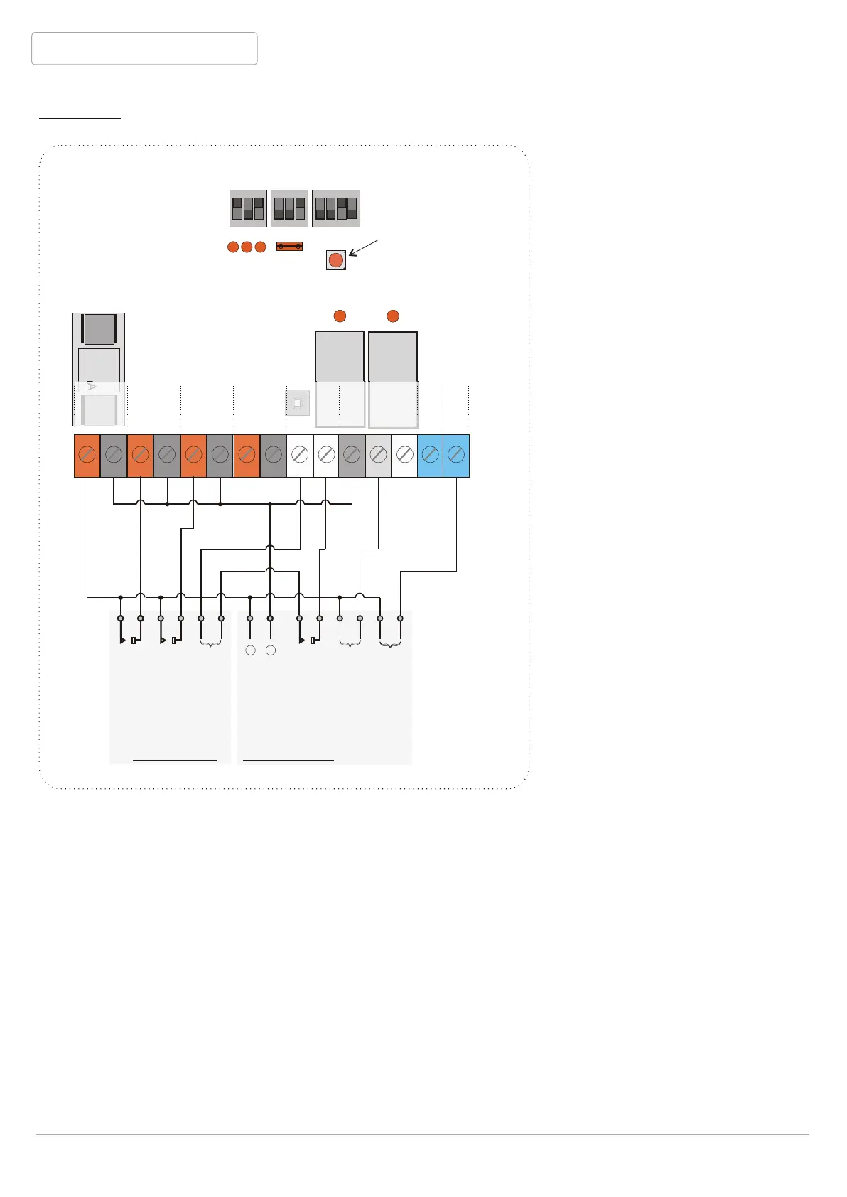
Diagram 3: Alarm system with relay outputs and external dialer to report
a technical failure and alarm.
OKout
Tmp
Read switch
dips
Red jump
PaninV
GrdinV
F2
ONON
11 22 33
ONON
11 22 33
ONON
11 22 33
44
500mA
AlinV
Read
OKout
Grdout
Alout
Tmpout
Grdin
Panin
Alin
Supply
Ta
P+
A+
G+
+
Tb
P-
A-
G-
-
COM
NC
NO
A B
C
Alarm contact
Guard contact
Sabotage
loop
Tampercontact
Input technical
failure to dialer
Input channel to
report (fog) alarm
12 V in
+
_
Alarm central External dialer
Dip switches:
A1:Position ON = unit in
guard only if there is
12V over [Grdin].
So if relevant output
of the central is
active(relay-contact
closed), GrdinV LED
is lit and BANDIT is in
guard mode.
A2: Position OFF = if
there is a transition
of 12V to 0 V over
[Alin] (contact opens)
while BANDIT is in
guard, the alarm
mode is activated.
This means fog
ejection during
adjusted period (dip
block C). [Alout]
becomes [Supply-].
for 3 minutes. During
these 3 minutes, the
input for alarm report
of the dialer gets 12
V and is activated for
this period.
A3: Position ON = only 12V over [Panin] can activate panic mode. Not connected, so no
function.
B1: No connection of remote control, so no function.
B2: No connection of remote control, so no function.
B3: No Control box connected, so position ON.
C1 OFF, C2 OFF, C3 ON and C4 OFF = adjusted fog ejection period is 4 seconds (see p. 25).
The technical failure input of the dialer gets 12V as long as there is a BANDIT failure through
the NC contact of [Okout].