FIVE POSITION PHOENIX CONNECTOR
Control I/O - The five pin phoenix connector can be used when interfacing other equipment with the
Reference 5 S2. Equipment such as CK1.2 Keypads, an external amplifier, or devices that require a +12VDC
trigger.
+12VDC - +12VDC power supply for keypad or IR sensor
Ground - Common ground
RS-232 Xmit - RS-232 one-way transmit out
Data In - Infrared Data/Signal input
CTRL Out - 12VDC programmable trigger out
Note - The entire control output is capable of suppling a maximum of 12VDC @ 200 mA. Check to see
that the device(s) being connected to the control require 200 mA or less current.
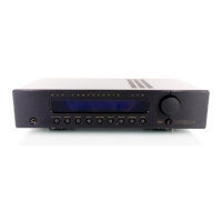
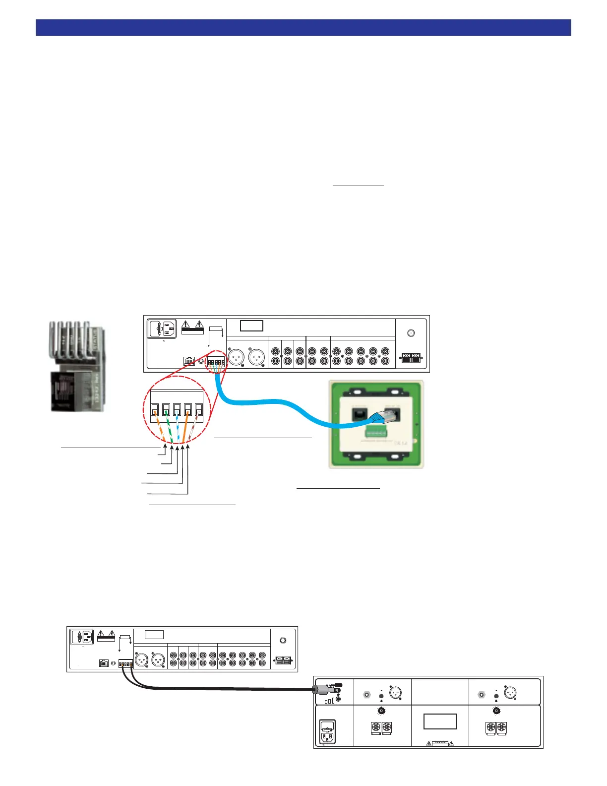
KEYPAD or IR SENSOR CONNECTION
To connect a CK1.2 Keypad to the Reference 5 S2, simply run a straight through CAT5 wire from the keypad
location to the Reference 5 S2. The keypad end of the CAT5 can be terminated into RJ-45. The keypad end
can also be terminated into the five position phoenix on the back of the keypad. Terminate the Reference 5
S2 end of the CAT5 cable manually into the phoenix connector. You can also order a RJ-45 to phoenix adap-
tor part number 21419 from B&K. See diagram below. If an IR sensor will be used, use the +12VDC GND
and IR Data to the IR sensor. RS-232 keypad status feedback is not functional on a Reference 5 S2.
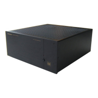
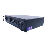
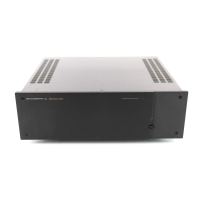
AMPLIFIER CONTROL TRIGGER
If it is desired to use an amplifier control trigger to remotely control an external amp, then the +12VDC and
GROUND should be terminated into an 1/8” (3.5mm) mono mini jack. Plug the mini jack into the amplifier
Control IN that is going to be controlled. If a keypad is also connected to the Reference 5 S2, the amplifier
control trigger can be connected in parallel with the control trigger. See diagram below.
8
ACCESSORIES
V1V2TV
SOURCE INPUTS
DVD
CD
INPUT
OUTPUT
TAPE
PREAMP OUTPUTS
FULL
RANGE
HIGH
PASS
SUB
MONO
L+R
Audio/Video Systems Hand-Made in the U.S.A.
BK&
SBIMPLY ETTER!
RISK OF ELECTRIC SHOCK
DO NOT OPEN
CAUTION
ANTENNA
AM
FM
VOLTAGE
RS-232
IR
OUTPUT
BALANCED OUTPUT
FULL RANGE
LEFT RIGHT
SERIAL #
GROUND
RS232 TRANSMIT
IR DATA INPUT
CONTROL OUT
+12V
AC LINE
200 mA Max
Current @ 12V
Using a EIA-T568B Cat-5 Cable
RJ-45 termination on one end
and bare wire on the other
CK1.2 Keypad Connection
Plug the male RJ-45 connector into the
port on the CK1.2 Keypad. Additional
keypads in a zone can be run out of the Slave [OUT].
Master
[IN] RJ-45
Reference 5 S2 Connection
Insert and tighten the wires into the
Control I/O Port five pin phoenix connector.
GR
RS2
IR
First Color is Primary Color (Secondary)
IR OUTPUT - Solid Orange
GROUND - Green / White Stripe & (Solid Green)
RS232 XMIT - White / Blue Stripe
+12V - Orange / White Stripe & (Solid Brown)
12V Control - White / Brown Stripe
Solid Blue = N/C
Note: If an IR sensor is
going to be used, only
+12VDC, GND and IR DATA
need to be connected
P/N - 21419
FUSE
CAUTION: FOR CONTINUED
PROTECTION AGAINST RISK
OF FIRE REPLACE ONLY WITH
SAME TYPE AND RATING.
CHANNEL 2 OUTPUTCHANNEL 1 OUTPUT
CHANNEL 1 INPUT CHANNEL 2 INPUT
CTRL
OUT
12VDC
200mA
CONTROL IN
ALL
OWS
AM
PLIFIER
OPERATION
W
HEN
A
5-24V
SIGNAL
IS
APPLIED
W
ITH
A
3.5mm
M
INI JACK
XLR (BALANCED)
RCA (UNBALANCED)
XLR (BALANCED)
RCA (UNBALANCED)
RCA INPUT
XLR INPUT
RCA INPUT
BK
&
SB
IMPLY ETTER!
SERIAL #
CTRL
IN
RISK OF ELECTRIC SHOCK
DO NOT OPEN
RISK OF ELECTRICSHOCK
DO
NOT OPEN
AC LINE
POSITIVE
NEGATIVE
POSITIVE
NEGATIVE
CONTROL I/O
www.bkcomp.com
High Performance
Audio/Video Systems
Hand-Made in the U.S.A.
+12V
L
OW
P
OWER
RING
TIP
GROUND
SLEEVE
+12VCTRL E
NABLE
XLR INPUT
Reference 200.2 S2
V1V2TV
SOURCE INPUTS
DVD
CD
INPUT
OUTPUT
TAPE
PREAMP OUTPUTS
FULL
RANGE
HIGH
PASS
SUB
MONO
L+R
Audio/Video Systems Hand-Made in the U.S.A.
BK
&
SB
IMPLY ETTER!
RISK OF ELECTRIC SHOCK
DO NOT OPEN
RISK OF ELECTRIC SHOCK
DO
NOT OPEN
CAUTION
ANTENNA
AM
FM
VOLTAGE
RS-232
IR
OUTPUT
BALANCED OUTPUT
FULL RANGE
LEFT RIGHT
SERIAL #
GROUND
RS232 TRANSMIT
IR DATA INPUT
CONTROL OUT
+12V
AC LINE
200 mA Max
Current @ 12V
 Loading...