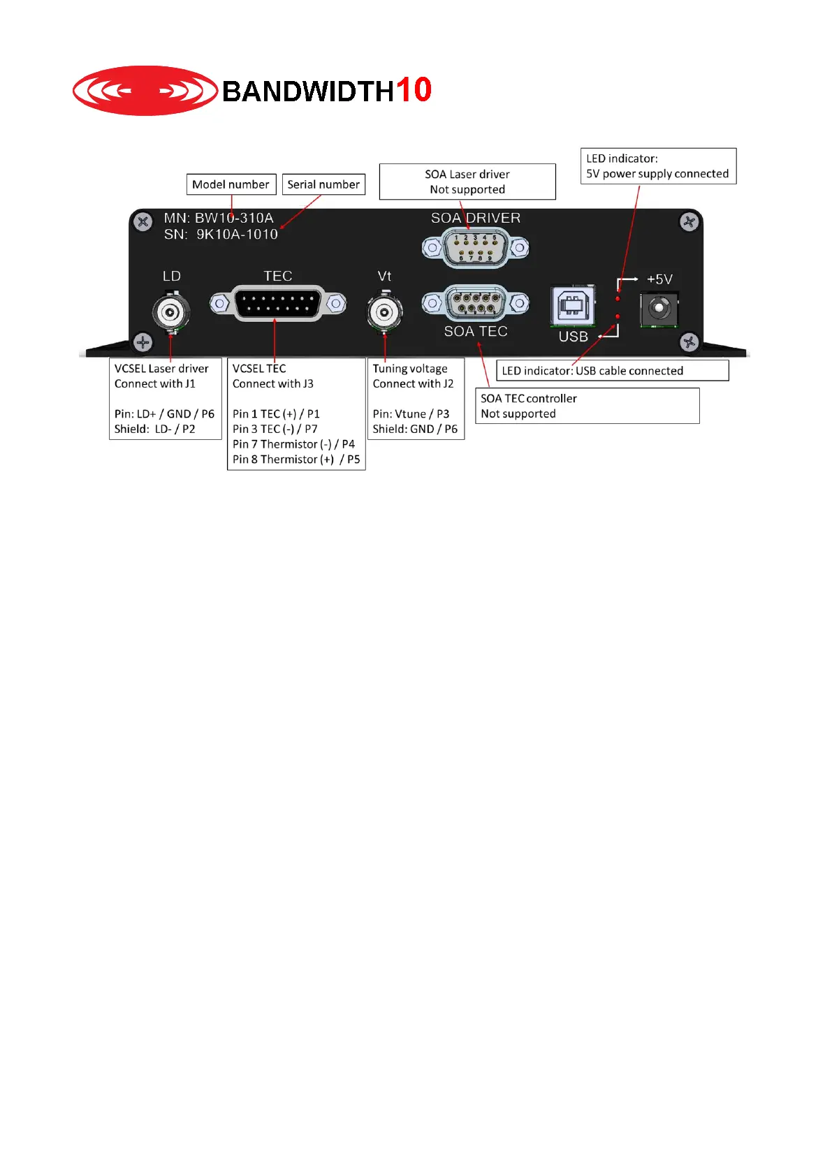
Backside:
Hardware setup
Please follow the steps in order, “DO NOT” proceed to a next step without completing a previous step
1. Please ensure proper ESD precautions. Please wear an ESD wrist strap and use an ESD protection
mat.
2. Do not insert laser in the fixture at this stage.
3. Connect LD with J1 of the TO fixture –
You must not use BNC couplers to extend the BNC cable length. When using BNC couplers
and the metal housing is placed on an optical bench you will generate a short or ground loop
which will damage the laser.
4. Connect Vt with J2 of the TO fixture – Do not use BNC couplers to extend the BNC cable length.
You must not use BNC couplers to extend the BNC cable length. When using BNC couplers
and the metal housing is placed on an optical bench you will generate a short or ground loop
which will damage the laser.
5. Connect TEC with J3 of the TO fixture
6. Optional: Connect SOA Driver and TEC outputs with a Thorlabs LM14S2 fixture
7. Connect the 5V power supply to the wall outlet, connect the power connector with the barrel
connector. The LED should be on.
8. Connect the USB cable with the box and the computer. Connect only if +5V LED is on
9. Start GUI
10. Insert Laser according to instructions in the GUI section.
Please note that LD pin and LD shiels as well as Vt pin and Vt shield are shorted when the pin protection is
on.