Do you have a question about the Bandwidth10 BW10-310A and is the answer not in the manual?
Details the key capabilities and specifications of the BW10-310A VCSEL driver.
Lists all the components and accessories included in the product package.
Emphasizes ESD precautions and initial checks before connecting hardware.
Guides on connecting VCSEL driver, TEC, tuning voltage, power, and USB interfaces.
Details the necessary Java Runtime Environment (JRE) version for the GUI.
Provides instructions for launching the GUI and establishing a COM port connection.
Explains how to set temperature, current, and voltage for VCSEL and SOA.
Guides on selecting sweep type, setting limits, and sweep frequency.
Covers enabling TEC, laser current, and final laser insertion into the fixture.
The BW10-310A is a versatile VCSEL driver designed for precise control of Vertical Cavity Surface Emitting Lasers (VCSELs), offering integrated TEC (Thermo-Electric Cooler) control and a swept voltage generator. This device is engineered to support a range of VCSEL wavelengths, specifically 1060 nm, 1550 nm, and 1654 nm families, making it suitable for various optical applications.
The core function of the BW10-310A is to provide a stable and controllable current source for anode-grounded VCSELs, capable of delivering up to 30mA. This current control is essential for driving the VCSELs to their desired optical output power. Beyond simple current delivery, the device incorporates an integrated TEC controller, which is crucial for maintaining the VCSEL's operating temperature within a specified range. Temperature stability is vital for consistent laser performance, wavelength stability, and device longevity. The TEC controller ensures that the VCSEL operates at its optimal temperature, compensating for environmental fluctuations and self-heating effects.
A key feature of the BW10-310A is its integrated swept voltage generator. This generator provides a dynamic voltage sweep function, supporting various waveform shapes including sinusoidal, triangular, and square root. The swept voltage capability is particularly useful for applications requiring wavelength tuning or modulation of the VCSEL. For 1060 nm VCSEL families, the device can generate swept voltages up to +40V, while for 1550 nm and 1654 nm products, it supports sweeps up to -20V. This flexibility in voltage sweep allows for precise control over the VCSEL's tuning characteristics. The device includes a 60Msamples 8-bit arbitrary waveform generator, enabling the creation of complex sweep signals at frequencies up to 120KHz. This advanced waveform generation capability allows users to tailor the voltage sweep to specific experimental or application requirements, offering a high degree of control over the VCSEL's dynamic behavior.
The BW10-310A is designed to be used in conjunction with the BW10-420C test fixture, ensuring proper electrical and thermal interfacing with the VCSEL. It operates on a single 5V power supply, simplifying its integration into existing setups. The device also features integrated pin protection, safeguarding the VCSEL and the driver from potential damage due to incorrect connections or electrical transients.
The BW10-310A is managed through a Graphical User Interface (GUI), which provides a user-friendly platform for controlling all aspects of the device. The GUI is designed with several safety restrictions to prevent accidental damage to the laser. For instance, it prevents users from enabling a current or TEC setting that is unsuitable for the connected device or from enabling the laser current without first enabling the TEC circuit. If an unsafe operation is attempted, a pop-up window will explain the exception, guiding the user towards safe operation.
The quick start guide outlines a clear sequence of steps for setting up and operating the device. Users begin by opening the GUI and establishing a connection to the device via a COM port. Once connected, the GUI displays the device's firmware version and confirms the board connection, indicated by a green background. The GUI also shows the status of the pin protection, which is enabled by default when no component is loaded.
A crucial step in the setup involves selecting the appropriate VCSEL wavelength/type (e.g., 1550 nm) within the GUI. This selection is critical as it refines the maximum laser drive and tuning voltage limits, ensuring that the user does not exceed the safe operating conditions for their specific laser. The GUI allows users to set precise limits for LD (Laser Diode) current and Vt (Tuning Voltage), which are essential for protecting the laser from overcurrent or overvoltage. For 1550 nm and 1654 nm VCSELs, the tuning voltage limits must be entered with a negative sign, reflecting the anode-grounded configuration of the driver.
After setting the wavelength and limits, the laser is inserted into the fixture, ensuring a good thermal connection. Unchecking the "load/unload" box in the GUI disables the pin protection, allowing the user to enable the VCSEL TEC controller. Both the VCSEL and SOA (Semiconductor Optical Amplifier) TEC controllers are enabled with the same circuit, streamlining temperature management.
The GUI then allows users to enable the laser current and/or tuning voltage. This involves entering the desired values into the respective fields and clicking "update" or "enter." The GUI also supports different modes for tuning voltage, including "Manual" for a constant DC voltage and "Arbitrary" for swept voltage generation. When "Arbitrary" is selected, users can choose from sinusoidal, triangular, or square root waveforms and define the minimum and maximum voltage limits for the sweep. The sweep frequency can also be set, with options for Hz or kHz units. The GUI ensures that the upper and lower voltage limits are rounded to the nearest voltage setting supported by the hardware, and users are prompted to load these values into the microcontroller. To initiate a sweep, users enter the desired frequency and click "START SWEEP." The GUI also provides visual feedback, indicating whether the voltage settings and waveform shape can be changed once a sweep is in progress.
The BW10-310A emphasizes safety and protection throughout its design and operation. Integrated pin protection is a key maintenance feature, automatically shorting J1 and J2 to GND when no component is loaded. This mechanism prevents damage to the laser and driver during handling or when the device is idle. The pin protection is disabled only after a component is loaded and the "load/unload" button is clicked, ensuring that the laser is protected during critical stages of setup. The GUI also allows users to change maximum/minimum operating conditions, wavelength, or box type only when the component is unloaded and pin protection is active, further enhancing safety.
The device's design includes robust ESD (Electrostatic Discharge) precautions. Users are advised to wear an ESD wrist strap and use an ESD protection mat during hardware setup to prevent damage to sensitive components. The GUI itself is designed to prevent incorrect connections or operations that could lead to ESD damage.
The software installation process is straightforward, requiring Oracle's Java 8u191 version or earlier, which supports the serial communication library without licensing fees. This ensures compatibility and ease of use. The GUI does not require a complex installation; users simply unzip the files and run a batch file. If the GUI fails to start, instructions are provided to check and correct the Java path, ensuring smooth software operation.
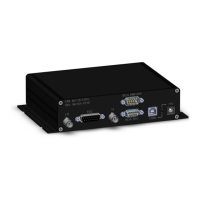
The device's modular design, with clear connections for LD, TEC, Vt, and USB, simplifies troubleshooting and maintenance. The LED indicators for 5V power supply and USB cable connection provide immediate visual feedback on the device's status, aiding in quick diagnosis of power or connectivity issues. The shipping list includes all necessary cables and a wall mount power supply with interchangeable AC blades, ensuring that users have the correct accessories for global use. The optional D-Sub 9 cables for SOA connection provide flexibility for advanced setups, while the inclusion of BNC cables and a D-Sub 15 cable ensures comprehensive connectivity.
The manual explicitly warns against using BNC couplers to extend cable length, as this can generate a short or ground loop, potentially damaging the laser. This guidance is a crucial maintenance tip, preventing common user errors that could lead to device failure. Similarly, the note regarding LD pin and LD shield, as well as Vt pin and Vt shield being shorted when pin protection is on, provides important information for users to understand the device's protective mechanisms.
Overall, the BW10-310A is designed for reliable and safe operation, with features that support both precise control of VCSELs and ease of maintenance.
| Fuel Type | Gasoline |
|---|---|
| Engine Type | 4-Stroke OHV |
| Fuel Tank Capacity | 4.0 gal |
| Noise Level | 68 dB |
| Rated Watts | 3100 W |