Do you have a question about the Bang & Olufsen BEOGRAM 4002 and is the answer not in the manual?
Details the manual's content, structure, and component designation system.
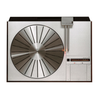
Provides detailed technical specifications for the Beogram 4002.
Visual guide for taking the Beogram 4002 apart.
Explains the record wiping feature in STAND BY mode.
Details the circuit for controlling turntable motor speed via a generator.
Describes the power amplifier and voltage regulation for motor speed.
Explains the logic for automatic speed switching based on record size.
Details the circuit controlling the magnet coil for arm movement.
Describes the stabilized power supply for the CD-4 demodulator.
Explains the function of the carrier detector circuit.
Details the PLL lock-in range and the matrix for signal mixing.
Explains the circuit ensuring silent outputs when the pickup arm is not lowered.
Describes the electronic switch for CD-4 record detection.
Adjusting turntable bearing height and vertical alignment.
Adjusting the chassis for proper parallel alignment with the cover plate.
Adjusting the electronic position marker and magnet coil system.
Procedure for fixing the horizontal placement of the pickup arm.
Adjusting static balance and ensuring pickup arm parallelism.
Adjusting the detector arm and the pickup arm's turning.
Adjusting the arm lowering position and damper cylinder speed.
Adjusting the diaphragm for precise pickup arm lowering.
Adjusting the spindle parallelism and lubrication chart.
Procedure for adjusting 33 and 45 RPM speeds using potentiometers.
Adjusting the voltage on the collector of 4IC1 in the photo Darlington circuit.
Lists instruments and calibration steps for the CD-4 generator.
Step-by-step procedure for adjusting the ANRS system.
Procedure for adjusting the carrier wave detector for optimal performance.
Adjusting the silent circuit and fine-tuning the carrier wave detector.
Flowchart for diagnosing issues when no record is present.
Flowchart for diagnosing slide transport and pickup arm problems.
Flowchart for diagnosing issues related to pickup arm movement speed.
Diagram showing the main mechanical components of the Beogram.
List of mechanical parts with corresponding numbers and descriptions.
List of mechanical parts with corresponding numbers and descriptions.
List of mechanical parts with corresponding numbers and descriptions.
Lists of components for various PC boards.
Alternate exploded view diagram with different part numbering.
List of mechanical parts with corresponding numbers and descriptions.
List of mechanical parts with corresponding numbers and descriptions.
Lists of components for specific PC boards.
Lists parts not shown in diagrams and corrections to the parts list.
List of resistors for PC board 1.
List of transistors, diodes, and ICs for diagram 1.
List of components for PC board 6.
List of resistors and capacitors for PC board 1.
List of components for PC boards 3, 4, and 8.
Modification to improve automatic lowering circuit reliability.
Adjustment for detector arm circuit due to component tolerances.
List of transistors, diodes, and ICs for diagram 2.
Lists of transistors, diodes, and ICs for diagram 2.
Table showing functions activated by the Beomaster 2400 remote control.
Details the electrical circuit operation for the PHONO button.
Details the electrical circuit operation for the STAND BY button.
| Platter | Aluminum |
|---|---|
| Model | BEOGRAM 4002 |
| Drive system | Belt drive |
| Speeds | 33, 45 rpm |
| Cartridge | Moving magnet |
| Output | Line level |