3.1.2 Models
Models Cellular Carrier ISM Radio Inputs and Outputs
DXM100-A1-V Verizon
None
Four universal inputs: Sinking/sourcing discrete, 4–20mA analog, 0–10 V analog,
counter, and/or temperature with a 10 kOhm thermistor
Four NMOS outputs, two 0–10 V analog outputs, and two DC Latching outputs
Two adjustable 5 V to 24 V switched power outputs, one SDI switched power
outputs, and one 5 V courtesy power output
DXM100-A1-A AT&T
DXM100-A2R1-V Verizon 900 MHz
Performance
Gateway
DXM100-A2R1-A AT&T
An LTE cellular modem is installed in the DXM100-A1 or DXM100-A2 Controller.
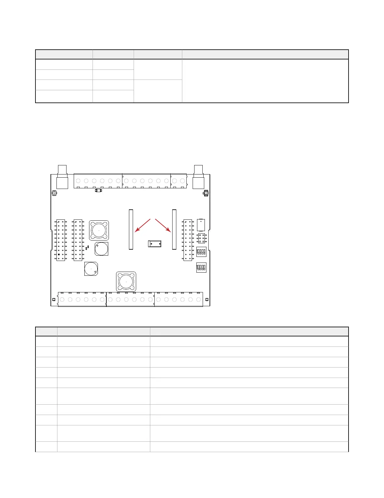
3.1.3 I/O Base Board for the DXM100-Ax
Figure 6. I/O base board for the DXM100-A1 and -A2 models
ON
ON
1
1
1
1
1
1
1
1
LED2
TB1
C6
R82
TB4
P2
P4
SW1
C4
P5
SW2
P10
TB3
P7
TB2
TB9
Y1
P6
L2
TB5
TVS1
L1
R77
P9
P8
P1
LED1
P3
A
B
C
D
G
H
J
K
L
1
18
19
32
M
L
Pin
Name Description
1 No Connection Not used
2 PW. 12-30 V DC or solar power in (+) Main power in for DXM Controller, can be 12-30 V DC or solar power (20 W panel max)
3 GD. Ground DXM ground
4 B+. Battery in (< 15 V DC) 12 V battery connection, positive
5 GD. Ground DXM ground
6 M-. Primary RS-485 -
Modbus master port (+) controlled by the DXM Controller. DXM can read/write Modbus slave
devices connected to this port.
7 M+. Primary RS-485 + Modbus master port (-)
8 GD. Ground DXM ground
9 1A. DLatch 1A
Input A (+) connection for first external DC latching solenoid. Use I/O board Modbus register 507
to control.
10 1B. DLatch 1B Input B (-) connection for first external DC latching solenoid
DXM Enclosure Kit (DEK) Series
8 www.bannerengineering.com - Tel: + 1 888 373 6767
 Loading...