EasyManua.ls Logo

Banner Expert D12EP6FV User Manual

Default Icon
12 pages
To Next Page IconTo Next Page
Page #1 background imageLoading...
Page #1 background image
D12 Expert Series – TEACH-Mode Fiber Optic Sensors
One-button programmable sensors for use with glass or plastic fibers
Printed in USA P/N 41974G8B
**NOTE:9 m (30') cables are available by adding suffix “W/30” to the model number of any cabled sensor (e.g., D12EN6FP W/30)
D12 Expert Series Glass Fiber Optic Models
D12 Expert Series Plastic Fiber Optic Models
Models
Switching Threshold
Setting
Cable**
Supply
Voltage
Output Type Maximum Range
D12EN6FV
Just above the “dark”
condition
2 m (6.5') 10-30V dc
NPN (sinking)
Range varies by sensing mode and fiber
optics used; see page 11.
D12EP6FV PNP (sourcing)
D12E2N6FV
Midway between “dark”
and “light” conditions
NPN (sinking)
D12E2P6FV
PNP (sourcing)
D12EN6FP
Models
Switching Threshold
Setting
Cable**
Supply
Voltage
Output Type Maximum Range
Just above the “dark”
condition
2 m (6.5') 10-30V dc
NPN (sinking)
Range varies by sensing mode and fiber
optics used; see page 12.
D12EP6FP PNP (sourcing)
D12E2N6FP
Midway between “dark”
and “light” conditions
NPN (sinking)
D12E2P6FP PNP (sourcing)
IMPORTANT: SEE SAFETY USE WARNING ON PAGE 4
D12 Expert Features
Fiber optic sensors for DIN rail mounting; 10 to 30V dc operation
Visible red (680 nm) light source; models for use with either glass or plastic fibers
High optical sensing power when needed, also excels at low-contrast sensing
Easy TEACH-mode programming automatically adjusts sensitivity to optimal setting*
D12E sensors are designed for low-contrast sensing applications (switching
threshold set to just above the “dark” condition)
D12E2 sensors set their switching threshold midway between the “dark” and
“light” conditions to ignore subtle changes, such as web flutter
Output may be programmed for either light or dark operate
Fast 200 microsecond sensing response; Programmable 40 millisecond pulse
stretcher
Secure one-button programming is easy to use; one button sets both TEACH and
sensor configuration settings
7-segment LED bargraph indicates relative received signal strength and sensing
contrast, programming status, and diagnostic trouble warnings
Marginal sensing alarm
Separate input allows remote programming by an external device, such as a
switch or a process controller
*U.S. Patent #5808296
Question and Answer IconNeed help?

Do you have a question about the Banner Expert D12EP6FV and is the answer not in the manual?

Banner Expert D12EP6FV Specifications

General IconGeneral
Input Voltage10-30 V DC
Cable Length2 m
OutputPNP
IP RatingIP67
Sensing ModeDiffuse
ConnectionCable
Light SourceRed LED
Supply Voltage10 to 30V DC

Summary

D12 Expert Features

Key Product Features Overview

Details sensor capabilities, light source, sensing power, and programming features.

D12 Expert Series Overview

Sensor Overview and Self-Diagnostics

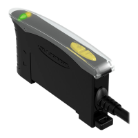
Introduces the D12 Expert sensors, their one-button programming, and LED status display.

D12 Expert Series Programming Modes

TEACH Mode Overview

Explains how TEACH mode automatically sets sensitivity for optimal sensing.

Output Configuration Overview

Details programming output timing (0/40ms) and operate modes (LO/DO).

Sensor Programming Procedures

Output Configuration Programming Steps

Details programming output timing and light/dark operate using the push button.

TEACH Mode Programming Steps

Provides step-by-step instructions for teaching sensing conditions and contrast indication.

Safety and Warnings

Personnel Safety Disclaimer

States sensors are not safety devices and must not be used for personnel protection.

Sensor Dimensions and Mounting

Fiber Optic Model Dimensions

Provides physical dimensions for glass and plastic fiber optic models.

Mounting Bracket Details

Details the mounting bracket and DIN rail mounting options.

D12 Expert Wiring and Operation

NPN and PNP Output Wiring Diagrams

Shows hookup diagrams for NPN (sinking) and PNP (sourcing) output configurations.

RUN Mode and Basic Operation

Explains RUN mode, the LED display as a signal strength indicator, and default settings.

Remote Programming Capabilities

Remote Programming Interface

Explains how to connect a remote switch to program TEACH and OUTPUT CONFIGURATION modes.

Remote Programming Timing Diagrams

Illustrates timing diagrams for single-, double-, and triple-clicks for remote control.

Self-Diagnostics and Troubleshooting

Diagnostic Indicators and Issues

Describes LED indications for marginal sensing, overloaded output, faulty data, and component failure.

Fiber Optic Accessories

Glass Fiber Models and Specifications

Lists available glass fiber sizes, typical models, maximum range, and sensing tip dimensions.

Plastic Fiber Optic Accessories

Plastic Fiber Models and Specifications

Lists available plastic fiber sizes, typical models, maximum range, and sensing tip dimensions.

Related product manuals