EasyManua.ls Logo

Banner TL70 User Manual

Default Icon
4 pages
To Next Page IconTo Next Page
Page #1 background imageLoading...
Page #1 background image
Quick Start Guide
This guide is designed to help you set up and install the TL70 Modular Tower Light. For complete informaon on programming, performance,
troubleshoong, dimensions, and accessories, please refer to the Instrucon Manual at www.bannerengineering.com. Search for p/n 182214 to view the
Instrucon Manual. Use of this document assumes familiarity with pernent industry standards and pracces.
Conguring the Modules
1
2 3 4 5 6 7 8
9
10
Turn on the appropriate DIP switch to set the order of the components, counng up from the tower light's base.
Module 1
Module 2
Module 3
Module 4
Module 5
Module 6
Base
Assembly Opons
DIP Switches
1 2 3 4 5 6 7 8
Light and Standard
Audible
Components
Module 1 ON
Module 2 ON
Module 3 ON
Module 4 ON
Module 5 ON
Module 6 ON
Light Module Flash
Rate
3 Hz ON OFF
1.5 Hz ON ON
Solid On* OFF OFF
Standard Audible
Module Sengs
Pulse 1.5 Hz ON OFF
Chirp Alarm ON ON
Siren Alarm OFF ON
Connuous
Alarm*
OFF OFF
Assembly Opons
DIP Switches
1 2 3 4 5 6 7 8 9 10
Loud Audible
Module
Sengs
Pulse 1.5 Hz ON OFF
Chirp Alarm ON ON
Siren Alarm OFF ON
Connuous
Alarm*
OFF OFF
Low Intensity OFF OFF
Med. Intensity ON OFF
Med./Loud
Intensity
OFF ON
Loud Intensity ON ON
* Factory default seng
TL70 Modular Tower Light
Original Document
182215 Rev. G
10 October 2017
182215
Question and Answer IconNeed help?

Do you have a question about the Banner TL70 and is the answer not in the manual?

Banner TL70 Specifications

General IconGeneral
TypeTower Light
Housing MaterialPolycarbonate
Light SourceLED
Input ProtectionReverse polarity protection
Light Segments5 segments
Response Time< 100 ms
Color TemperatureVaries by color
Dimensions70 mm diameter
Lifespan50, 000 hours

Summary

Quick Start Guide

Configuring the Modules

Details how to set the order of tower light components using DIP switches.

Assembling the Modules

Wiring Diagrams

Specifications

Supply Voltage and Current

Details electrical requirements and current draw for different colors and audible modules.

Audible Alarm Settings

Explains how DIP switches control audible alarm frequency and intensity.

Supply Protection Circuitry

Outlines protection against transient voltages and indicator response times.

Indicator Characteristics

Lists color, wavelength, and lumen output for various indicator colors.

Vibration and Mechanical Shock

Specifies resistance to vibration and shock according to industry standards.

Required Overcurrent Protection

Details necessary overcurrent protection for electrical connections.

Connections

Describes the types of connectors and wiring available for the modules.

Operating Conditions

Specifies the environmental operating parameters like temperature and humidity.

Environmental Rating

States the ingress protection rating (IP65).

Certifications

Lists the product's certifications (CE, cULus).
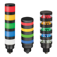
Banner Engineering Corp. Limited Warranty

Related product manuals