EasyManua.ls Logo

Banner EZ-SCREEN LP User Manual

Banner EZ-SCREEN LP
74 pages
To Next Page IconTo Next Page
Page #1 background imageLoading...
Page #1 background image
EZ-SCREEN
®
LP
Low-Profile Safety Light Screen
Instruction Manual
Original Instructions
Section Contents
Section 1 Introduction .............................Page 1
Section 2 Components and Specifications ..............Page 6
Section 3 Installation and Alignment ..................Page 21
Section 4 System Operation ........................Page 42
Section 5 Troubleshooting and Maintenance ...........Page 48
Section 6 Checkout Procedures .....................Page 53
Section 7 Cascadeable EZ-SCREEN LP ..............Page 55
Features
A two-piece optoelectronic safeguarding device•
Creates a screen of synchronized, modulated infrared •
sensing beams that extend from end to end of the
housing (no “dead” zone)
Low-profile, compact package for smaller production •
machines, robust for large power presses
Choose standard or cascadeable models •
14 mm or 25 mm resolution; defined areas from 270 to •
1810 mm0to)
00mmtomto• ') sensing range
Easily configured reduced resolution and fixed blanking. •
Remote Teach of fixed blanking option on cascade
models.
Zone and Status indicators plus digital display to indicate •
number of beams blocked, detailed diagnostics
Highly immune to EMI, RFI, ambient light, weld flash, and •
strobe light
Selectable 1-ch, 2-ch, or no external device monitoring •
Selectable auxiliary output option to monitor the state of •
the OSSDs or monitor receiver and emitter lockouts
Selectable emitter test option simulates a “blocked” •
condition
Vibration-tolerant, factory burned-in emitter and receiver •
circuitry for toughness and dependability
FMEA tested to ensure control reliability•
Up to four pairs of SLPC.. model emitters and receivers •
can be cascaded
Safety PLC input compatible (per OSSD specifications)•
Low-Profile Safety Light Screen
Buy: www.ValinOnline.com | Phone 844-385-3099 | Email: CustomerService@valin.com

Table of Contents

Question and Answer IconNeed help?

Do you have a question about the Banner EZ-SCREEN LP and is the answer not in the manual?

Banner EZ-SCREEN LP Specifications

General IconGeneral
TypeLight Screen
Resolution14mm, 20mm, 40mm
Operating Voltage24V DC
Response Time≤ 20ms
Housing MaterialAluminum
Protection RatingIP65
Number of Beams8 to 120

Summary

Important Safety Information

Read Before Installation

Emphasizes reading all safety and installation instructions before system setup.

1. Overview

1.1 Introduction

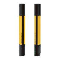
General introduction to the EZ-SCREEN LP light screen.

1.2 Applications and Limitations

Details product use cases and restrictions.

1.3 Control Reliability

Explains system reliability features like redundancy and self-checking.

1.4 Operating Features

Lists key product functionalities like blanking and EDM.

2. Components and Specifications

2.1 14 mm Models (Non-Cascadeable)

Lists 14mm non-cascadeable emitter and receiver models.

2.2 25 mm Models (Non-Cascadeable)

Lists 25mm non-cascadeable emitter and receiver models.

2.3 Cordsets

Details available cables and connectors for system interface.

2.4 Accessories

Lists optional add-on items for system enhancement.

2.5 Replacement Parts

Lists available spare parts for the system.

2.6 Literature

Lists related documentation and manuals.

2.7 Specifications

Provides detailed technical specifications for the system.

3. Installation and Alignment

3.1 Mechanical Installation Considerations

Discusses physical mounting factors like safety distance and guarding.

3.2 Mechanical Mounting Procedure

Step-by-step guide for physically mounting sensors.

3.3 Initial Electrical Connections

Guide for initial wiring and connections.

3.4 Light Screen Initial Checkout

Procedure for initial system verification before machine connection.

3.5 Electrical Interface to the Guarded Machine

Details connecting the system to the guarded machine.

3.6 Preparing for System Operation

Steps required before the system can be put into operation.

3.7 Sensor "Swapability"

Features for sensor interchangeability and emitter hookup.

4. System Operation

4.1 Security Protocol

Defines roles for system operation and maintenance.

4.2 System Configuration Settings

How to set up system parameters via DIP switches.

4.3 Reset Procedures

Steps for performing system resets.

4.4 Status Indicators

Explains system status lights and diagnostic displays.

4.5 Normal Operation

Describes standard operating states and modes.

4.6 Periodic Checkout Requirements

Schedule for performing system checks.

5. Troubleshooting and Maintenance

5.1 Troubleshooting Lockout Conditions

Guide for resolving lockout conditions and errors.

5.2 Test Mode

Using test mode for diagnostics and verification.

5.3 Electrical and Optical Noise

Addresses potential issues caused by electrical or optical noise.

5.4 Servicing and Maintenance

Discusses cleaning procedures and warranty service.

6. Checkout Procedures

6.1 Schedule of Checkouts

Outlines different checkout types and their frequency.

6.2 Commissioning Checkout

Procedure for initial system setup checkout.

6.3 Shift/Daily Checkout

Daily checks for system status and operation.

6.4 Semi-Annual Checkout

Six-month checks for system installation and changes.

7. Cascadeable EZ-SCREEN LP

7.1 Overview of Cascading

Introduction to cascading light screen systems.

7.2 Cascadeable Models – 14 mm Resolution

Lists 14mm cascadeable emitter and receiver models.

7.3 Cascadeable Models – 25 mm Resolution

Lists 25mm cascadeable emitter and receiver models.

7.4 Determining Interconnect Cordset Lengths

Guide for selecting appropriate cable lengths for cascades.

7.5 Response Time for Cascaded Screens

Calculating response times for cascaded systems.

7.6 Cascaded Sensor Configuration Settings

Configuring scan codes, EDM, and other settings for cascades.

7.7 Configuration for Cascaded Operation

Steps for setting up cascaded systems.

7.8 Emergency Stop Buttons and Devices

Integrating emergency stop buttons into cascade systems.

7.9 Positive-Opening Safety Switches

Using safety interlock switches with cascade inputs.

7.10 Remote Fixed Blanking

Remote programming of fixed blanking feature.

Appendix A. Bracket Assembly Instructions

Glossary of Terms

1.4 Operating Features

1.4.1 Selectable Trip/Latch Output

How to choose between trip and latch output modes.

1.4.2 Emitter Hookup Options

Details ways to connect the emitter.

1.4.3 External Device Monitoring (EDM)

Details EDM functionality and configurations.

1.4.4 Remote Test Input

Using the remote test function for setup.

1.4.5 Scan Code Configuration

Setting scan codes to prevent crosstalk.

1.4.6 Reduced Resolution (Floating Blanking)

1.4.7 Status Indicators

1.4.8 Manual Resets and Lockout Conditions

1.4.9 Fixed Blanking

1.4.10 Inverted Display

1.4.11 Cascadeable Models

Alignment Aids

LAT-1-LP Laser Alignment Tool

Laser tool for sensor alignment.

Snap-On Lens Shields

Protective shields for sensor lenses.

EZ-LIGHT ™ for EZ-SCREEN

Accessory Mounting Brackets

MSM Series Corner Mirrors

SSM Series Corner Mirrors

MSA Series Stands (Base Included)

2.7 Specifications

2.7.1 General Specifications

Overall technical specifications including safety and environmental ratings.

2.7.2 Emitter Specifications

2.7.3 Receiver Specifications

3.1.1 Safety Distance (Minimum Distance)

Reduced Resolution Impact on Distance

Effect of reduced resolution on safety distance calculation.

3.1.2 Pass-Through Hazards

3.1.3 Reset Switch Location

3.1.4 Supplemental Safeguarding

3.1.5 Emitter and Receiver Orientation

3.1.6 Adjacent Reflective Surfaces

3.1.7 Use of Corner Mirrors

3.1.8 Installation of Multiple Systems

3.2 Mechanical Mounting Procedure

3.2.1 Sensor Mounting

Steps for physically mounting the emitter and receiver.

Mounting the End-Cap Brackets

Specifics on installing end-cap mounting brackets.

Mounting the Side-Mount Brackets

3.2.2 Mounting the Reset Switch

3.2.3 Routing Cables

3.4 Light Screen Initial Checkout

3.4.1 Initial Power-Up and Optical Alignment

Steps for initial power-up and optical sensor alignment.

3.4.2 Reduced Resolution (Floating Blanking)

3.4.3 Fixed Blanking

3.4.4 Trip Test

3.5 Electrical Interface to the Guarded Machine

3.5.1 OSSD Output Connections

Connecting the OSSD safety outputs to machine control.

3.5.2 FSD Interfacing Connections

Connecting Final Switching Devices (FSDs) for safety.

3.5.3 Machine Primary Control Elements and EDM Inputs

Connecting control elements and EDM inputs.

External Device Monitoring Hookup

One-Channel Monitoring

EDM configuration for one-channel monitoring.

Two-Channel Monitoring

EDM configuration for two-channel monitoring.

No Monitoring

EDM configuration for no monitoring.

3.5.4 Remote Test Input

3.5.5 Auxiliary Output

3.6 Preparing for System Operation

3.7 Sensor "Swapability"

Status Indicators for Cascaded Applications

4.5 Normal Operation

4.6 Periodic Checkout Requirements

5. Troubleshooting and Maintenance

5.1 Troubleshooting Lockout Conditions

Guide for resolving lockout conditions and errors.

5.1.1 Receiver Error Codes

5.2 Test Mode

5.1.2 Emitter Error Codes

5.3 Electrical and Optical Noise

5.4 Servicing and Maintenance

6. Checkout Procedures

6.1 Schedule of Checkouts

Outlines different checkout types and their frequency.

6.2 Commissioning Checkout

Procedure for initial system setup checkout.

6.3 Shift/Daily Checkout

Daily checks for system status and operation.

6.4 Semi-Annual Checkout

Six-month checks for system installation and changes.

7. Cascadeable EZ-SCREEN LP

7.1 Overview of Cascading

Introduction to cascading light screen systems.

7.1.1 System Components and Specifications

Components for cascaded systems.

7.1.2 Receiver Display

Display indications for cascaded receivers.

7.2 Cascadeable Models – 14 mm Resolution

7.3 Cascadeable Models – 25 mm Resolution

7.4 Determining Interconnect Cordset Lengths

7.5 Response Time for Cascaded Screens

Individual Response Time and Safety Distance

Calculating individual response time and safety distance.

Overall Response Time and Safety Distance

Calculating overall cascade response time and safety distance.

7.6 Cascaded Sensor Configuration Settings

7.6.1 Fixed Blanking

Configuring fixed blanking for cascaded sensors.

7.7 Configuration for Cascaded Operation

7.8 Emergency Stop Buttons and Devices

E-Stop Switch Requirements (Positive-Opening)

Requirements for positive-opening E-stop switches.

7.9 Positive-Opening Safety Interlock Switches

Monitoring Series-Connected Safety Switches

Monitoring multiple safety switches in series.

7.10 Remote Fixed Blanking

Remote Fixed Blanking Programming Procedures

Procedures for programming fixed blanking remotely.

Appendix A. Bracket Assembly Instructions

Glossary of Terms

Related product manuals