Overview
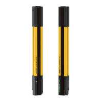
EZ-SCREEN LP
Instruction Manual
Appendix A
Figure A-1. End-mount hardware attachment
Figure A-2. Side-mount hardware attachment
End-Mount Brackets
(2 supplied with each emitter and receiver)
M3 x 10
Torque to 9 in-lbs (1.0 N-m)
M3 x 6
Torque to 7 in-lbs (0.8 N-m)
Appendix A. Bracket Assembly Instructions
The screwdriver provided with the EZ-SCREEN LP is intended for access to the DIP switches and for preassembly of the mounting
braketsinalassembltihtenin)ofthemontinbraketsholbeaomplisheithaPhillipssreriverormm
Üqefk*t ^iibaî�kr q�aofsbo�ql �^` efbsb�qeb�ifpqba�ql onr b�pmb`fä`^qfl kp+�Pbkpl op�j ^v�_b�j l r kqba�t fqe�pfab*j l r kq�_o^` hbqp)�bka*j l r kq�
brackets, or a combination of both.
Side-Mount Brackets
(2 or more*
supplied with each
emitter and receiver
)
Bracket
Clamp
M3 x 10
Torque to 9 in-lbs (1.0 N-m)
M3 x 6
Torque to 9 in-lbs
(1.0 N-m)
No bracket
mounting here
Brackets may be
mounted within
this area
No bracket
mounting here
Ensure that clamp assembly
is fully seated onto
“dovetail” feature on
side of housing.
* Side brackets must be used
with longer sensors, if they are
subject to shock or vibration.
In such situations, the sensors
are designed to be mounted
with up to 690 mm unsupported
distance (between brackets).
Sensors 830 mm and longer
are supplied with one or more
additional side brackets for
center-mounting (see manual,
Section 3.2.1).
Note proper
orientation
Buy: www.ValinOnline.com | Phone 844-385-3099 | Email: CustomerService@valin.com
 Loading...