Overview
EZ-SCREEN LP
Instruction Manual
Cascadeable EZ-SCREEN
Remote Fixed Blanking Programming Procedures
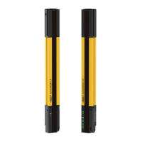
Prior to performing these procedures, install the EZ-SCREEN
LP per Section 3 of this document, including all other DIP switch
configuration settings (T/L, RR, and Scan Code). Align the E/R
pair and perform all required checkout procedures to ensure
proper operation. Ensure that the EZA-RBK-1 programming key
switch is rotated to the counter-clockwise position (Run position,
see Figure 7-11) at power-up and normal operation.
Important:
1.The first sensing beam (synchronization beam) at the display
end of the sensor must remain clear.
2. The number and location of blocked beams is indicated by the
receiver’s 7-segment display and the zone indicators. If the
configuration is reliable, this number should not change.
3. A reset switch (e.g., a normally open switch) must be used to
complete some programming procedures below.
•• •••• ••• •• • •• • • •• • •• •• • •• • • • •• •• • • •• • •• •• • •• • • •• •• •• • •• • • • • ••• • ••• •• ••• • ••• ••• • •• • •••••••••••••••••••••••••••••••••••••••••••••••••••••••••••••••••••••••••••••••••••••
The following procedures must be completed within 10 minutes or a lockout will occur (Error Code 12 will be displayed).
Action Indication Comments
1 Locate the obstruction in the defined
area and secure it.
EZA-RBK-1: OFF
Receiver: number and location of blocked
beams is indicated by the 7-segment
display and the zone indicators.
If the configuration is reliable, this
number should not change.
2 Turn the programming key switch
to the Program position (clockwise)
momentarily (> ¼ second) and then
return to the Run position.
EZA-RBK-1: ON (key in Program position),
then slowly flashes for approximately
5 seconds (key returns to Run position).
Receiver: display indicates “P” “F” “C”
This “teaches” and saves the new
fixed blanking configuration.
3 Trip Output: the OSSDs turn ON.
Latch Output:
After the EZA-RBK-1
indicator turns OFF, a valid reset
sequence is required to turn ON the
OSSDs
.
EZA-RBK-1: OFF
Receiver: display indicates normal
operation. (See Section 3.4.3, step 9.)
• • •• • • • • • ••• • •• • • •• ••• ••• •• • • ••• • • • • • ••• • • • •• • • •• • • • •• •• • • •• • •••••••••••••••••••••••••••••••••••••••••••••••••••••••••••••••••performthefollowingsteps:
The following procedures must be completed within 10 minutes or a lockout will occur (Error Code 12 will be displayed).
Action Indication Comments
1
Place the programming key switch in
the Program position (clockwise) until
step 3.
EZA-RBK-1: ON
Receiver: sequences between “P” “F” “A” and
the number of blocked beams
.
EZA-RBK-1 indicator steady ON
indicates program mode.
2
Locate or relocate the obstruction (e.g.
tooling, fixturing, etc.) in the defined
area and secure. If clearing the fixed
blanked area, remove all obstructions.
EZA-RBK-1: ON
Receiver: display sequences between “P” “F”
“A” and the number of blocked beams.
I
f an Error code 12 occurs
(programming time out), go to step #6
below (do not return the programming
key switch to the Run position at this
time).
3
Return the programming key switch to
the Run position (counter-clockwise)
.
EZA-RBK-1: slowly flashes, approximately 5
seconds
Receiver: display indicates “P” “F” “C”
This saves the new fixed blanking
configuration.
4
Trip Output: the OSSDs turn ON.
Latch Output: After the EZA-RBK-1
indicator turns OFF, a valid reset
sequence is required to turn ON the
OSSDs
.
EZA-RBK-1: OFF
Receiver: display indicates normal operation
if fixed blanking is removed. Otherwise, see
Section 3.4.3, step 9.
Buy: www.ValinOnline.com | Phone 844-385-3099 | Email: CustomerService@valin.com
 Loading...