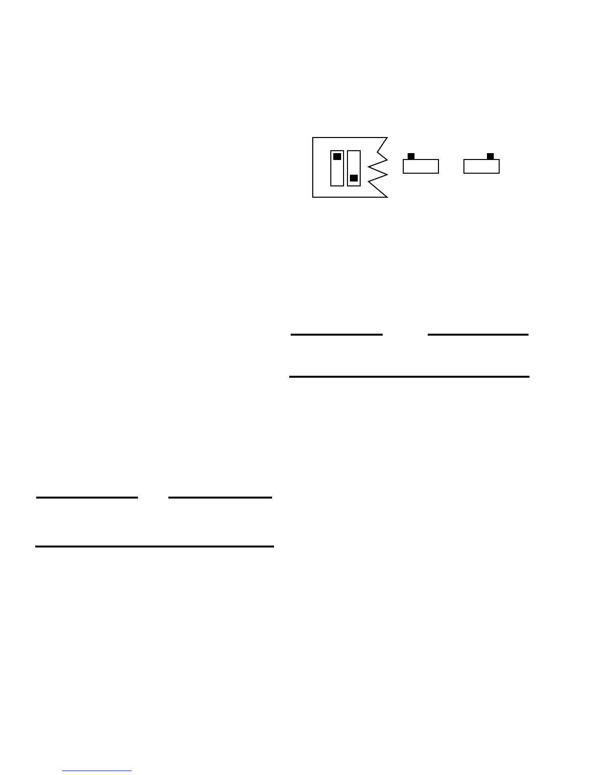
Side View
"On"
ON OFF
Side View
"Off"
OFFON
O
N
O
F
F
Top View
S1 S2
5.5 PROPER PROCEDURES FOR SETTING SWITCHES S1
AND S2
Question: How do I know if the switches in the dual-in-line
packages are correctly set as far as being in the OFF position
or the ON position?
Answer: The drawings above should clarify any confusion
about switch settings. The easiest way to set the switches is to
apply pressure with a small pointed object until the switch clicks
into position.
CAUTION
As a safety measure, the engine should be equipped with
an independent overspeed shutdown device in the event
of failure which may render the governor inoperative.
10
NOTE
For some diesel engines, better operation may be
obtained by placing SW1 in "ON" position. If
difficulty is experienced in "OFF" position, try SW1
ON and recalibrate.
5.3 ALL CONTROLLERS WITH REVISION J AND ABOVE
HAVE SWITCHES S1 AND S2
These units have two new features now added to the DYN1
1065X series controllers. They are:
5.3.1 Two response ranges, for matching either the diesel or
gas engine dynamics.
• Set S1 to the OFF position for diesel engine applications.
• Set S1 to the ON position for gas/gasoline engine
applications.
5.3.2 Two actuator selections, so the same controller can be
used on the DYNA 8000, DYNA 8200 or DYNA 8400 actuator.*
• Set S2 to the OFF position when using a DYNA 8000
actuator.
• Set S2 to the ON position when using a DYNA 8200 or DYNA
8400 actuator.
5.4. GENERAL INFORMATION ON S1 AND S2
• Switch S1 selects one of two integrating rate ranges. The
diesel version integrates at twice the rate of the gas version
• Switch S2 selects the point at which actuator coil current
level causes the integrator limit to be actuated. This level
is nominally 6.3 amperes for the DYNA 8000 and 7.3 am-
peres for the DYNA 8200 and 8400 actuator.
* DYNA 8000 -- DYNC 11020 Series
DYNA 8200 -- DYNC 12000 Series
DYNA 8400 -- DYNC 14800 Series
These actuators do not have a potentiometer feedback
transducer.

 Loading...