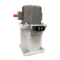
6. CALIBRATION PROCEDURE FOR 8000 GOVERNOR CONTROLLER —
DYN1-10682, 10683, 10684, 10686
DYN1-10682-000-0-12/24
DYN1-10682-001-0-12/24*
DYN1-10683-000-0-12/24
DYN1-10683-001-0-12/24*
Input Signal
Frequency
Maximum
Input Signal
Frequency
Maximum
Part Number
Part Number
DYN1-10684-000-0-12/24
DYN1-10684-001-0-12/24*
DYN1-10686-000-0-12/24
DYN1-10686-001-0-12/24*
2500 to 5000 Hz
5000 to 9000 Hz
250 to 1200 Hz
1200 to 2500 Hz
WARNING
For gas engines, make certain that method used
does not put gas in exhaust which might result in
an explosion.
6.1 CALIBRATION PROCEDURE
6.1.1 Observe that potentiometer settings are adjustable from
zero to 100%. Each small division is 10%. The speed potenti-
ometer is 10K, 20 turn.
6.1.2 Set the small dip switch, S1, for the correct engine. (See
paragraph 6.4) Set switch S2 in the "OFF" position for actuator
DYNA 8000 or in the "ON" position for DYNA 8200 and 8400.
6.1.3 If a remote speed potentiometer is used for narrow
range, set to mid range.
6.2 INITIAL POTENTIOMETER SETTINGS
GAIN 20%
I 20%
D 30%
DROOP Zero
6.2.1 For isochronous operation, set DROOP counterclock-
wise to minimum position as shown in paragraphs 3.5 and 3.6.
6.2.2 For DROOP operation, set DROOP potentiometer clock-
wise to obtain desired amount of DROOP from no-load to full
load. Turning potentiometer clockwise increases DROOP.
6.3 START ENGINE (NO LOAD)
6.3.1 Adjust the controller speed potentiometer for desired
engine speed.
6.3.2 Adjust the GAIN potentiometer clockwise until the en-
gine begins to hunt. (If the engine remains stable at 100%
GAIN, physically disrupt the actuator linkage by hand.) With
the engine hunting, turn the GAIN potentiometer counterclock-
wise until stable.
6.3.3 Repeat step 6.3.2 for the "D" setting.
6.3.4 Repeat step 6.3.2 for the "I" setting.
]
]
]
]
NOTE
See Step 6.4 for proper procedures for setting switches S1
and S2, if you have a controller that has the two switches
located on top of the controller.
11
6.3.5 After calibration, it may be necessary to readjust the
speed.
6.3.6 Following the above calibration, conduct the following
test. With the engine operating at rated speed, turn the electric
governor off. When engine speed slows to approximately half
of rated speed, turn the electric governor back on. Observe the
overshoot. If there is a small hunt at steady state, slightly turn
the "I" potentiometer counterclockwise until stable. In some
cases, 2 to 3 Hz overshoot may be acceptable.
If possible, operate the unit through various load ranges up to
100% to ensure stability.
6.4 CONTROLLERS HAVE SWITCHES S1 AND S2
These units have two new features now added to the DYN1
1068X series controllers. They are:
6.4.1 Two response ranges for matching either the diesel or
gas engine dynamics.
• Set S1 to the OFF position for diesel engine applications.
• Set S1 to the ON position for gas/gasoline engine
applications.
6.4.2 Two actuator selections, so the same controller can be
used on the DYNA 8000, DYNA 8200 or DYNA 8400 actuator.*
• Set S2 to the OFF position when using a DYNA 8000
actuator.
• Set S2 to the ON position when using a DYNA 8200 or DYNA
8400 actuator.
*

 Loading...