=
Input Signal
Frequency in Hertz
3
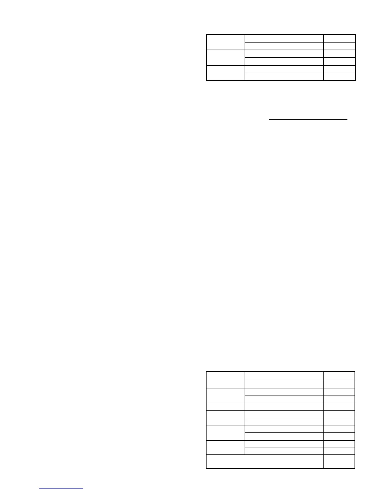
2.1.10 DYNA 8000 CONTROLLER
Nominal Quiescent Current 80 mA
Maximum Amperes @ Stall 13 amps
Nominal Quiescent Current 80 mA
Maximum Amperes @ Stall 13 amps
Kilograms 0.863
Pounds 1.9
Output Current
@ 24 VDC
Weight
Output Current
@ 12 VDC
2.1.11 DYNA 8000 CONTROLLER
INPUT SIGNAL FREQUENCY
Engine RPM x Number of Gear
Teeth on Flywheel
60 Seconds
Select controller for the correct input signal frequency range
generated by the magnetic pickup at the maximum engine
operated (RPM) speed.
2.1.12 AVAILABLE CONTROLLER MODELS
Controllers: Speed Input Signal Frequency
• DYN1-10652-000-0-12/24 250 - 1200 Hz
• DYN1-10653-000-0-12/24 1200 - 2500 Hz
• DYN1-10654-000-0-12/24 2500 - 5000 Hz
• DYN1-10656-000-0-12/24 5000 - 9500 Hz
• DYN1-10682-000-0-12/24 250 - 1200 Hz
• DYN1-10683-000-0-12/24 1200 - 2500 Hz
• DYN1-10684-000-0-12/24 2500 - 5000 Hz
• DYN1-10686-000-0-12/24 5000 - 9500 Hz
2.2. DYNA 8000 & DYNA 8000 UL APPROVAL,
HAZARDOUS DUTY, CLASS 1, DIVISION 2, GROUP D
ACTUATOR SPECIFICATIONS
2.2.1 Operating Voltage: 12 VDC or 25 VDC ±20%
2.2.2 Ambient Operating Temperature:
-65 to +255°F (-55 to +125°C).
2.2.3 Sealed Unit: Oil, water and dust tight.
2.2.4 Connection: Terminal strip or "MS" Connector.
2.2.5 Mechanical Vibration: 5 to 500 Hz, Curve F, per
MIL-STD. 810D, Method 514-2.
2.2.6 DYNA 8000 ACTUATORS
Joules 1.2
Foot-Pounds 0.9
Newton-Meters 1.4
Pound-Foot 1.0
Rotary 35°
Kilograms 5
Pounds 11.0
Maximum Amperes @ Stall 12.5
Nominal Steady State Amperes 3.5
Maximum Amperes @ Stall 9.5
Nominal Steady State Amperes 1.5
Nominal Response Time for 63% of Stroke
(Seconds)
Current @
12 VDC
Current @
24 VDC
Torque
Output
Weight
Work
0.030
1. GENERAL INFORMATION
1.1 INTRODUCTION
The DYNA 8000, DYNA 8200 and DYNA 8400 governor system
provides an engine governor for speed and power control of
piston and gas turbine engines or steam and water turbines.
The actuator is a simple, proportional, electric solenoid having
a sliding armature whose magnetic force is proportional to input
coil current. The armature glides on anti-friction bearings and is
balanced between the force of its return spring and the mag-
netic force, thus providing a hysteresis-free linear movement.
The linear motion is converted to an output shaft rotation by a
crank arm.
The hazardous duty DYNA 8000 and DYNA 8400 actuators
provide units that are UL listed for Class I, Division 2, Group D,
hazardous duty applications that are often encountered in the
petroleum or chemical industries. The hazardous duty actua-
tors can be used to provide an engine governor for speed and
power control of piston and gas turbine engines.
1.2 TYPICAL APPLICATIONS
Typical applications are speed governing, remote throttle con-
trol, generator sets, power carts and pump set applications.
1.3 STANDARD FEATURES
• All electric
• All engine compatible
• Mounts in any position
• Engine mounted (actuator only)
• High reliability due to few moving parts
• Proportional actuator
• No hydraulic or oil lines
• No special maintenance
• Spring returns output shaft to minimum position on removal
of power or loss of magnetic pickup signal
• Precise repeatability
2. SPECIFICATIONS
2.1 CONTROLLER SPECIFICATIONS
2.1.1 Operating Voltage: 12 VDC or 24 VDC ±20%
2.1.2 Ambient Operating Temperature:
-40 to +180°F (-40 to +85°C).
2.1.3 Temperature Stability: Better than ±0.5% over a
temperature range of -40 to +167°F (-40 to +75°C).
2.1.4 Steady State Speed Band: ±0.25%
2.1.5 Adjustments: Speed, Gain, Integral, and Droop.
2.1.6 Circuit Boards: Boards are covered with a heavy
conformal coating for moisture and vibration protection.
2.1.7 Connection: Terminal strip.
2.1.8 Mechanical Vibration: Withstands the following vibra-
tion without failure of degraded performance: 0.06 inch double
amplitude at 5 to 18 Hz; 1 G at 18 to 30 Hz; 0.02 inch double
amplitude at 30 to 48 Hz; 2.5 G's at 48 to 70 Hz.
2.1.9 The same DYN1-1065X or DYN1-1068X Series can be
used on a DYNA 8000, DYNA 8200 or DYNA 8400 actuator.
The DYN1-1068X governor control box provides a wider range
of adjustment than the DYN1-1065X. The DYN1-1068X can be
used where maximum performance is desired or for some
engines which are possibly more difficult to control.

 Loading...