1640-IN-026-A-00 Page 3 of 10
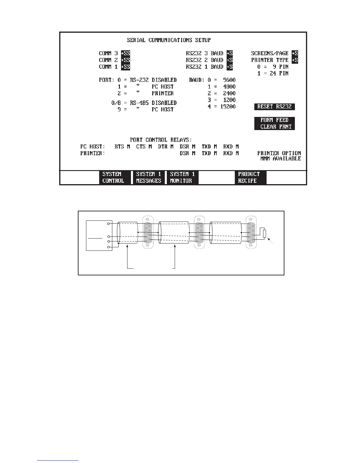
Figure 2.4 SERIAL COMMUNICATIONS SETUP SCREEN
DEVICE
NODE 1
DEVICE
NODE X
DEVICE
NODE 2
MACO SPI Port
SHIELD
4
ISOCOM
3
DATA (-)
2
DATA (+)
1
3
1
9
8
3
1
5
4
3
1
5
4
3
1
9
8
3
1
5
4
Termination
Resistor
100 Ohms
9
8
9 Pin Female Connectors (Rear View)
Beldon 8772 Cable
Figure 2.5 Wire multiple Device's
2.5 Wiring
The SPI Auxiliary Interface module uses a four pin connector
to communicate with the devices. Connector E23-1134-004
is provided with screw terminals for field wiring. Figure 2.5
illustrate the device wiring, note the SPI module terminals are
not in order, see Figure 2.2.
The RS-485 cabling shall run on the low voltage side of the
MACO controllers cable tray located at the bottom of each
chassis.
The Device that is located farthest from the MACO require a
bus terminator resistor, see Figure 2.5.
 Loading...