1640-IN-026-A-00 Page 9 of 10
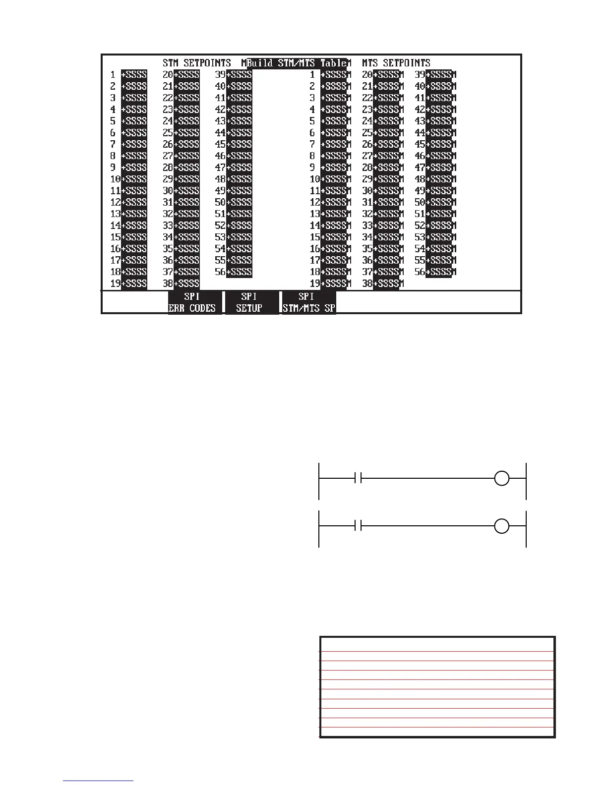
Figure 4.2 STM & MTS Control Relays Screen
4.2 STM/MTS control relays
There are 56 user-definable STM control relays (CR# 3777 -
3832) and 56 user definable MTS relays (CR# 3841 - 3896)
to be used in RLD. Any of the control relay commands read
back from the SPI equipment can be setup as a MTS, but only
those with a STM next to them (see 3.1.1 and 3.1.9) can be
setup as STM relays. MTS relays are typically setup in RLD
to monitor alarms or faults in the auxiliary equipment and react
accordingly in the RLD. STM relays are typically used in RLD
to turn on/off the auxiliary equipment and acknowledge alarms.
4.2.1 Building the STM/MTS Table
Table Figure 4.2, is used for defining which relays from the SPI
equipment are assigned as usable in RLD. The user can
define 56 MTS relays, with up to 32 MTS relays for a single
device. Refer to the bit definitions listed in table 1 for the
process status and machine mode commands for an additive
feeder as device one (1). If you wanted to assign the process
alarm of device number one as your first MTS relay, you would
enter a setpoint of 102. The one (1) represents the device
address number, and the 02 (bit number) is assigned to the
process alarm. If you wanted the process alarm from the
sixteenth (16) device, the setpoint entered would be 1602.
The first MTS setpoint entered links CR #3841 with the device
and bit definition encoded in the setpoint definition. There-
fore, you can assign CR #3841 in your RLD to react accord-
ingly based on your first MTS setpoint. The second setpoint
entered affects CR #3842. The user defines the CR meaning
based on the setpoints entered on this screen. For devices
with two control relay commands, the setpoints would range
from 100-131 for device address number one, and 3200-3231
for device address number thirty-two (32).
The user can also define up to 56 STM relays. Only those
control relay commands with a (STM) next to the command
can be setup. The setpoints range from 116-131 for device
address number one, and 3216-3231 for device address
number thirty-two (32). The setup of the STM relays is the
same as the MTS relays, except the setpoints entered affect
CR #3777 - CR #3832. In order to assign STM CR #3777 to
turn on/off your chiller at device address one, you would enter
a setpoint of 116 for STM setpoint number one.
CR #3841
PROCESS ALARM
(SPI DEV. 1 BIT 2 SP=102)
OUT 1
CR #1657
OPERATOR CR
CR #3777
CHILLER
ON/OFF
After you have defined all of your MTS and STM setpoints you
must activate the BUILD STM/MTS TABLE reverse video
area or energize CR #3769. Once the table is built CR #3833
will be energized. This is indicated by an asterisk next to the
build STM/MTS table. You must rebuild the table anytime you
change any MTS or STM setpoint.
MTS Control Relays STM Control Relays
3833 - STM/MTS table is built 3769 - Build STM/MTS table
3834 - Reserved 3770 - Reserved
3835 - Reserved 3771 - Reserved
3836 - Reserved 3772 - Reserved
3837 - Reserved 3773 - Reserved
3838 - Reserved 3774 - Reserved
3839 - Reserved 3775 - Reserved
3840 - Reserved 3776 - Reserved
3841 - 3896 = User define MTS 3777 - 3832 =User define STM
 Loading...