1640-IN-026-A-00 Page 7 of 10
3.2 Setup Screen
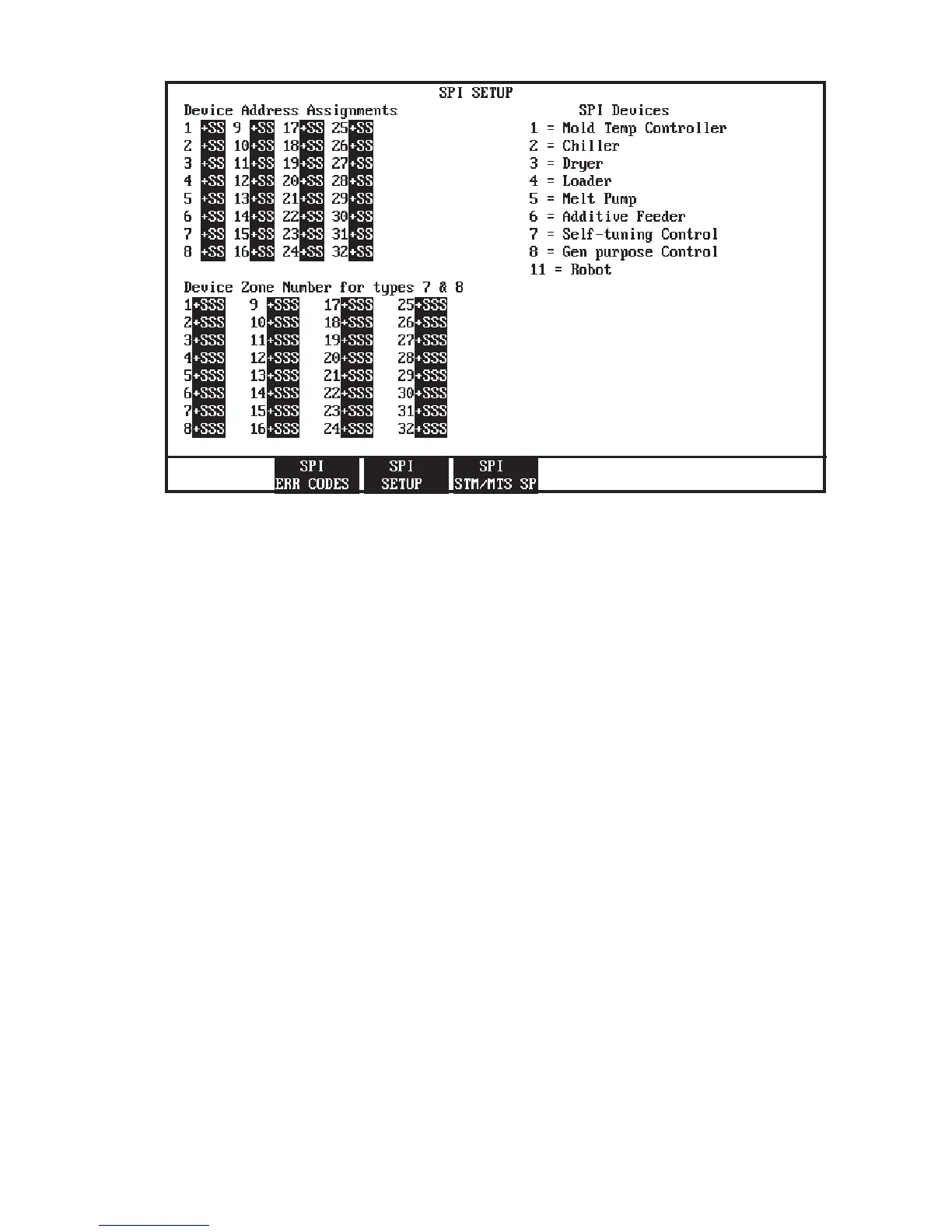
This screen allows the user to choose what SPI Auxiliary
Equipment device(s) will be communicating to the MACO.
The first setpoint entry in the device address assignments
section should correspond to your SPI equipment which you
have configured as device address 20 hex. Device 2 would
have device address 21 hex. If device address 20H is a dryer,
you should enter a setpoint of three (3) for this setpoint. You
continue entering setpoints for all of the SPI equipment you
wish to communicate with.
If your SPI device is a Self-Tuning or General Purpose
temperature controller types seven (7) or eight (8), you must
enter in a zone number for each zone of the controller you
wish to communicate with. A controller zone occupies one
device slot, for example if a Self-Tuning temperature control-
ler with 32 zones of control, you would enter in a seven (7) for
all 32 device address assignment setpoints, and a setpoint of
1 through 32 for each of the 32 device zone number setpoints.
If the 10th device on your SPI network is a self-tuning or
general purpose controller with three zones of control. Enter
a one (1) for the device zone number setpoint 10, for zone
setpoint 11 enter a two (2), and for zone setpoint 12 enter a
3. A seven (7) or eight (8) must be entered in the device
address assignment setpoint 11 & 12.
Note: The device zone number for type 7 & 8 setpoints could
be removed by the user with OptiGrafix if SPI device types 7
& 8 are not used.
Figure 3.2 Setup Screen
 Loading...