Manual 2100-614C
Page 6 of 40
the building will be controlled to an average of all
connected sensors. If there is more than 10F difference
from the highest to the lowest connected sensor, the
actual control will be governed by the hottest sensor for
cooling and the coldest sensor for heating.
If alarm boards are utilized, the highest reading of any
connected sensor will be used for high temperature
alarm and the lowest reading sensor will be used for low
temperature alarm. The on-board sensor is ignored if
two (2) or more sensors are connected to the Local, Rem
1 or Rem 2 sensor inputs.
SPECIFICATIONS/FEATURES FOR
ALARM BOARDS
MC4001-A w/Optional Base Alarm Board
(Inputs/Outputs)
NOTE: If this alarm board was not originally
factory installed, it can be field-installed at
anytime. Bard part number is AB3000-B.
NOTE: If this alarm board was not originally factory
installed, it can be field-installed at anytime. Bard
part number is AB3000-A.
Note: All alarm and output relays are dry contacts
rated 1A @ 24 VAC.
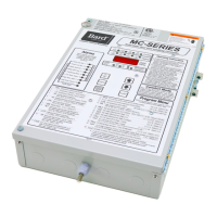
BASIC MC4001 CONTROLLER
INPUT/OUTPUT SPECIFICATIONS
MC4001 CONTROLLER CONNECTIONS
Located on Main Controller Board
Unit #1 C – 24VAC common
R – 24VAC hot
G – fan (Form A, NO)
Y1 – 1
st
-stage cool (Form A, NO)
Y2 – 2
nd
-stage cool (Form A, NO)
W – heat (Form A, NO)
Unit #2 C – 24VAC common
R – 24VAC hot
G – fan (Form A, NO)
Y1 – 1
st
-stage cool (Form A, NO)
Y2 – 2
nd
-stage cool (Form A, NO)
W – heat (Form A, NO)
F1-F2 Fire/smoke interface
Shipped with jumper installed (a)
48Vdc Back-up power input
-24Vdc or –48Vdc
-20V to –56V range
Local Main sensor, 12-inch leads
CU – copper, AG – silver
Polarity sensitive
Rem 1 Optional remote indoor sensor
CU – copper, AG – silver
Polarity sensitive
Rem 2 Optional remote indoor sensor
CU – copper, AG – silver
Polarity sensitive
Gen Generator interface G1-G2
Shipped with jumper installed (a)
H1-H2 Humidity controller input
Requires optional controller
Field installed
(a) These connections require either jumper or Normally
Closed (NC) relay contact at the Fire/Smoke and
Generator interface for Controller to function.
Inputs
Lockout 1 2,3 – input from HVAC #1
Lockout 2 2, 3 – input from HVAC #2
Outputs
Smoke/Fire Form C (SPDT)
Lockout 1 Form C (SPDT)
Refrigerant alarm HVAC #1
Lockout 2 Form C (SPDT)
Refrigerant alarm HVAC #2
Power Loss 1 Form C (SPDT)
Power loss HVAC #1
Power Loss 2 Form C (SPDT)
Power loss HVAC #2
Low Temp Form C (SPDT)
Low temperature alarm
High Temp 1 Form C (SPDT)
High temperature alarm #1
MC4001-B w/Enhanced Version Alarm Board
(Additional Outputs) plus MC4001-A Inputs/Outputs
Alarm relays can be wired for NO (close on alarm) or NC (open on alarm) strategy. Alarm relays can be used individually
if there are enough available building alarm points, or can be arranged into smaller groups or even a single group so that
all alarm capabilities can be utilized. When multiple alarms are grouped together and issued as a single alarm there will
be no off-site indication of which specific problem may have occurred, only that one of the alarms in the group has been
triggered. The individual alarm problem will be displayed on the LED display on face of the controller.
NOTE:
Sensors are
solid state,
not RTD.
Use Bard
sensors only.
Note: All alarm relay outputs have 10-second delay
before issuing to protect against nuisance alarm
signals.
High Temp 2 Form C (SPDT)
High temperature alarm #2
Controller Form C (SPDT)
Controller failure alarm
Econ 1 E, F - Form A (NO)
See note (b)
Econ 2 E, F - Form A (NO)
See note (b)
2
nd
Stage (c) Form C (SPDT)
2
nd
-stage cooling alarm
(b) Make these connections to terminals E & F
in HVAC 1 and 2 respectively if desired to have
economizers open for emergency ventilation at High
Temp Alarm #2 setpoint condition.
(c) For units with 2-stage compressors, 2nd stage
cooling alarm activates on cooling Stage 3 initiation.
 Loading...