Do you have a question about the Bard MC4002-BC and is the answer not in the manual?
Explains operation, installation, and troubleshooting of the MC4002 controller.
Describes the controller's function in managing two air conditioners for redundancy and equal wear.
Details FCC and CE compliance, and standards met by the MC4002 system.
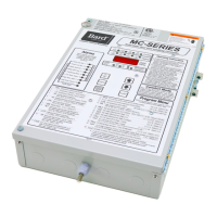
Outlines input power, outputs, stages, temperature ranges, and accuracy of the basic controller.
Provides guidance on the physical placement and installation of the controller unit.
Explains how local and remote sensors are used for temperature control and averaging.
Details terminal connections for units, sensors, generator, and humidity controller.
Lists inputs and outputs for optional Base and Enhanced Alarm Boards.
Describes the connection for disabling the MC4002 and shutting down units via fire suppression.
Details the built-in delays for cooling and heating stages.
Explains blower cycle control options and operation based on stages and sensors.
Describes how to swap lead and lag unit positions using the Advance button.
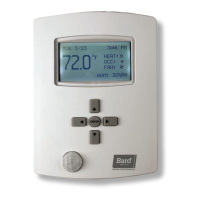
Explains the function of controller buttons for operation and programming.
Lists and defines programmable features and their default settings.
Details connecting a humidistat for synchronized dehumidification control.
Explains humidity control using hot gas reheat coils and a humidistat.
Sequences for 1 and 2-stage compressors with and without economizers.
Sequences for 2-stage compressors with and without economizers.
Describes heating operation for units with electric heat.
Describes heating operation for heat pumps with electric heat.
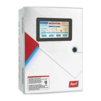
Details requirements and connections for the CB5000 Series Communication Board.
Describes accessing and viewing system status and configuring network IP settings.
Covers viewing and setting parameters, managing user access, and notification setup.
Configuring SNMP traps for remote alarm notifications and MIB file structure.
Guidance on wiring for different unit configurations and economizers.
Explains how to lock the controller to prevent unauthorized changes.
Describes signaling from a generator to lockout the lag unit.
Details the connection for maintaining operation during commercial power outages.
Wiring diagrams for 1-stage AC units without economizers and with JADE economizers.
Wiring diagrams for 2-stage WA*S/WL*S series AC units without economizers.
Wiring diagrams for W**HB/W**HC and WH/W**H/SH/S**H series heat pumps.
Wiring diagram for a single unit application with an alarm board.
Explains NO/NC wiring for alarms and grouping capabilities.
Details the availability and potential nuisance conditions of the 2nd stage cooling alarm.
Describes how to connect terminals for high/low refrigerant pressure lockout alarms.
Explains sequences for emergency ventilation using economizers.
| Brand | Bard |
|---|---|
| Model | MC4002-BC |
| Category | Controller |
| Language | English |