Manual 2100-614K
Page 10 of 61
2. If all stages of cooling are satised, and relative
humidity is above the set point of humidity
controller:
A. The green “Dehumidication Operation” light
will come on and the lag unit compressor (Y1
and Y2) and blower (G) will operate until the
setpoint of humidity controller is satised (or
cancelled by a call for cooling).
B. If the space temperature drops to 67°F, the
electric heater (W) of the lead unit will cycle
to help maintain building temperature. It will
cycle off at 69°F.
C. If space temperature drops to 64°F, the
Stage 2 Heating light will come on and
the lag unit compressor operating for
dehumidication mode will cycle off until the
building temperature rises above 65°F from
1st stage heat and building load. The green
“Dehumidication Operation” light stays
on during this sequence and when Stage 2
Heating light is Off, the compressor is On.
The electric heater in lag unit is locked out in
dehumidication mode.
Lag unit controller 24VAC outputs G, Y1 and Y2 are all
energized during dehumidication sequence. This is
true for both alternating and non-alternating controller
congurations.
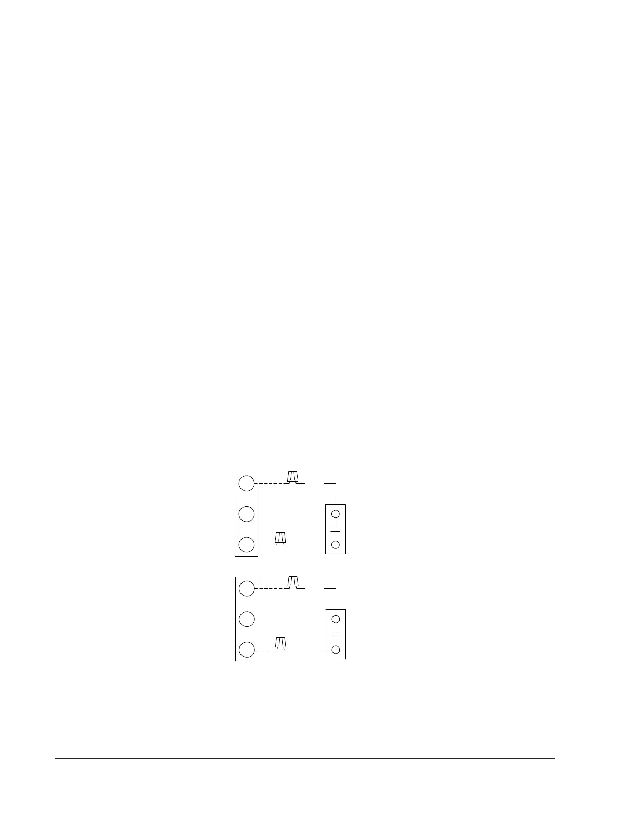
Hot Gas Reheat Dehumidication Option
A hot gas dehumidication wall mount air conditioning
system can perform dehumidication control by
addition of a humidistat that closes-on-rise, and is
connected to the “D” terminal on the unit low voltage
terminal strip. See Figure 2 for connection of the
humidistat. The recommended humidistat is Bard Part
#8403-038 or #8403-047. One or both units must be
equipped with the “D” hot gas reheat dehumidication
option. Dehumidication operation will be independent
from the MC4002 controller.
Sequence of operation with default set points:
1. Temperature control always has priority over
dehumidication regarding individual unit
operation. If there is any stage of cooling demand
active, the dehumidication sequence is locked out
by the wall mount unit. It is possible, however, if
only a single stage of cooling or heating is required
that can be met with operation of the lead unit, the
lag unit can still run in dehumidication mode.
2. If all stages of cooling are satised, and relative
humidity is above the setpoint of humidity
controller:
A. The humidistat will call for dehumidication
operation by sending a signal directly to
the wall mount unit (D). This operation will
continue until the humidity level falls below
the humidistat setpoint.
FIGURE 2
Electronic Humidistat Connection for "D" Dehumidication Models
C
D
R
C
D
R
C
D
R
MIS-4304
1.) SEPARATE HUMIDISTAT IS REQUIRED FOR "D" DEHUMIDIFICATION UNIT OPERATION.
LOW VOLTAGE TERMINAL STRIP CONNECTIONS PROVIDED IN UNIT INSTALLATION INSTRUCTIONS.
2.) TH, TS, CH, AND OLDER WA**/WH** MODELS DO NOT HAVE A "D" TERMINAL ON THE LOW VOLTAGE
MECHANICAL HUMIDISTAT CONNECTION FOR "D" DEHUMIDIFICATION MODELS
TERMINAL STRIP. MODELS THAT DO NOT HAVE THE "D" TERMINAL USE THE "W3" TERMINAL. REVIEW
"R" AND "DEH" TERMINALS.
INSTALL JUMPER BETWEEN
R
C
DEH
DEH
RED
YELLOW
YELLOW
RED
TERMINAL STRIP
VOLTAGE
PART #8403-038
HUMIDISTAT #1
PART #8403-038
HUMIDISTAT #2
UNIT #1 LOW
TERMINAL STRIP
VOLTAGE
PART #8403-047
HUMIDISTAT #1
UNIT #2 LOW
TERMINAL STRIP
NOTES:
C
R
VOLTAGE
UNIT #1 LOW
TERMINAL STRIP
VOLTAGE
PART #8403-047
NOTES:
HUMIDISTAT #2
UNIT #2 LOW
INSTALL JUMPER BETWEEN
DEH
LOW VOLTAGE TERMINAL STRIP CONNECTIONS PROVIDED IN UNIT INSTALLATION INSTRUCTIONS.
1.) SEPARATE HUMIDISTAT IS REQUIRED FOR "D" DEHUMIDIFICATION UNIT OPERATION.
2.) TH, TS, CH, AND OLDER WA**/WH** MODELS DO NOT HAVE A "D" TERMINAL ON THE LOW VOLTAGE
TERMINAL STRIP. MODELS THAT DO NOT HAVE THE "D" TERMINAL USE THE "W3" TERMINAL. REVIEW
ELECTRONIC HUMIDISTAT CONNECTION FOR "D" DEHUMIDIFICATION MODELS
MIS-4304B