2548H INSTRUCTION MANUAL
56-101-00420 Rev. C LOF
Nov
/ 07 / 14 Page viii
LIST OF FIGURES
Page
Figure 1 Identification Label ................................................................................... 1
Figure 2 Owner Warranty Registration Card .......................................................... 2
Figure 3 Limited Warranty Statement Card ............................................................ 3
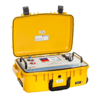
Figure 4 2548H AC Fuel Quantity Test Set ............................................................ 5
Figure 5 2548H Front Panel Components .............................................................. 6
Figure 6 Insulation Test, Configuration #1 ........................................................... 16
Figure 7 Insulation Test, Configuration #2 ........................................................... 16
Figure 8 Insulation Test, Configuration #3 ........................................................... 18
Figure 9 Insulation Test, Configuration #4 ........................................................... 18
Figure 10 Configuration of Capacitance Test ......................................................... 19
Figure 11 Individual Tank Unit Capacitance Test, Configuration #1 ...................... 21
Figure 12 Individual Tank Unit Capacitance Test, Configuration #2 ...................... 21
Figure 13 Capacitance Simulation, Configuration #1 ............................................. 23
Figure 14 Capacitance Simulation, Configuration #2 ............................................. 23
Figure 15 Capacitance Simulation, Configuration #3 ............................................. 24
Figure 16 System Calibration (Method 1), Configuration #1 .................................. 27
Figure 17 System Calibration (Method 1), Configuration #2 .................................. 27
Figure 18 System Calibration (Method 1), Configuration #3 .................................. 28



 To Next Page