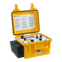
The Barfield TT1000A Turbine Temperature Test Set is a self-contained, portable, and multi-functional device designed for troubleshooting and calibrating aircraft Chromel Alumel (CH-AL) temperature indicating systems. It offers a comprehensive suite of testing capabilities, including thermocouple and system resistance measurement, insulation testing, indicator calibration, and temperature measurement.
Function Description:
The TT1000A is engineered to provide accurate and sensitive measurements for various aspects of CH-AL temperature systems. Its primary functions include:
- Resistance Measurement: Measures and displays the resistance of thermocouples, thermocouple rings, and system lead circuits. It can measure lead resistance from 0 to 19.99 Ω in 0.01 Ω increments (20 Ω range) and from 0 to 199.9 Ω in 0.1 Ω increments (200 Ω range).
- Insulation Testing: Measures and displays the insulation resistance of system wiring and other components, with a range of 0 to 1.999 MΩ in 1 kΩ increments.
- Thermocouple Simulation: Simulates CH-AL thermocouple outputs, with or without simulated system lead resistance, to test indicators. It can simulate system lead resistances from less than 2.0 Ω to greater than 250 Ω.
- Temperature Measurement: Measures and displays CH-AL thermocouple values directly in degrees Celsius (°C).
- Automatic Compensation: Automatically compensates for ambient temperature at the test lead connection junction point, or indicates this "cold junction" temperature, ensuring accurate readings.
Important Technical Specifications:
- Physical Characteristics:
- Size (H, W, L): 5.0 in. (12.7 cm), 5.5 in. (14.0 cm), 8.0 in. (20.3 cm)
- Weight: 4.0 lbs. (1.8 kg)
- Temperature Measurement (K (CH-AL) Thermocouple):
- Range: 0 to 1000°C certified, -25 to +1100°C extended; 0 to 1200°C certified, -25 to +1225°C extended with option D.
- Accuracy: Typical measurement error at 25°C ambient is less than ±1°C.
- NIST Conformity (Test Clip Linearization) Error:
- -25 to -21°C: Less than 2.0°C
- -20 to 0°C: Less than 1.0°C
- 0 to 90°C: Less than 0.6°C
- 91 to 169°C: Less than 1.0°C
- 170 to 1000°C: Less than 0.6°C
- 1001 to 1025°C: Less than 1.0°C
- 1026 to 1050°C: Less than 2.0°C
- 1051 to 1100°C: Less than 5.0°C
- Reference Junction Compensation Error (at test clips):
- 0 to 30°C: Less than 0.1°C
- 31 to 40°C: Less than 0.3°C
- 41 to 50°C: Less than 0.6°C
- Error Table (0 to 1000°C at 25°C ambient):
- Calibration Error: Less than 0.5°C
- Resolution & Repeatability: 1.0°C
- Total (Including Ref. Jct.): 1.5°C (+ NIST Conformity)
- Temperature Coefficient: 0.005% of Reading per °C
- Lead Resistance:
- 20 Ω Range: 0 – 19.99 Ω in 0.01 Ω increments
- 200 Ω Range: 0 – 199.9 Ω in 0.1 Ω increments
- Accuracy: ±0.1% of reading ±0.01 Ω (20 Ω Range); ±0.1% of reading ±0.1 Ω (200 Ω Range)
- Insulation:
- Range: 0 – 1.999 MΩ in 1 kΩ increments
- Accuracy: ±3% of reading ±0.003 MΩ
- Excitation: 45 VDC nominal
- Simulated System Resistance:
- Adjustment Range: Less than 2.0 Ω to greater than 250 Ω
- Fixed Setting: Less than 0.1 Ω
Usage Features:
- User-Friendly Interface: Features a large, 0.35 in. (9mm) high characters, 3 ½ digit Liquid Crystal Display (LCD) with preprogrammed legends for easy readability.
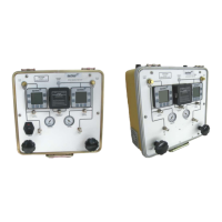
- Operating Controls:
- ON/OFF Switch (1): Applies power for all functions.
- TEMP. ADJ. Control Knob (3): A ten-turn potentiometer for exact adjustment of the millivoltage generator, displaying temperatures in °C when the FUNCTION switch is in INDICATOR TEST position.
- FUNCTION Switch (4): A three-position rotary switch for selecting RESISTANCE MEASURE, INDICATOR TEST, and TEMP. MEASURE functions.
- PUSH TO MEASURE ACFT. LEAD RES. BLACK Pushbutton (5): When depressed with test leads connected to the aircraft system and FUNCTION switch in RESISTANCE MEASURE, displays system resistance.
- SHORT TEST LEADS AND PUSH TO SET SYSTEM RES. RED Pushbutton (6): When depressed with shorted test leads and FUNCTION switch in RESISTANCE MEASURE, connects the SYSTEM RES. potentiometer for system resistance adjustment.
- RESISTANCE RANGE Switch (7): A four-position rotary switch for selecting resistance ranges (20 Ω, 200 Ω, 2 MΩ - 0 Ω system resistance) and BAT position for monitoring the 45-volt battery.
- SYSTEM RES. Control Knob (8): A ten-turn potentiometer for adjusting system lead resistance (2 to 250 Ω) when test leads are shorted and the red pushbutton is depressed.
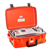
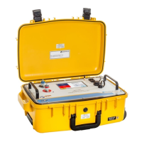
- Portability: Completely self-contained and easily portable, housed in a drawn aluminum carrying case for maximum strength. The lid design ensures the ON/OFF switch is moved to the OFF position when closed.
- Abridged Instructions: The lid contains a placard with abridged operating instructions for experienced technicians.
- Battery Check: Includes a battery check function to monitor the 45-volt battery for insulation testing and the six 1.5-volt batteries for other functions. A "BAT" warning indicates low battery life (approx. 10% remaining) for the 1.5V batteries.
- Protective Circuits: Equipped with PCB1 F1 (AGC ½A) to protect against overloads through test leads and PCB1 D1 to prevent accidental reverse polarity at battery replacement.
- Hot Engine Testing Procedure: Provides a method to circumvent errors caused by hot engines generating small potentials in thermocouples, by taking two measurements with reversed lead connections and averaging them.
Maintenance Features:
- Recertification Requirement: The Test Set has a one-year recertification requirement. Maintenance and calibration must be performed by qualified technicians in a shop equipped with necessary tooling and resources. Users are advised to contact Barfield for these services.
- Battery Installation/Replacement: Detailed instructions are provided for replacing the 6 AA Energizer® Alkaline E91 batteries and the 45-volt No. 415 (NEDA 213) battery. Cautions are given to prevent battery leakage, including not mixing old and new batteries, avoiding high temperatures, and removing batteries for long-term storage.
- Coin Battery: The "coin" battery has a minimum life expectancy of five years and is factory-installed. Instructions for safe removal are provided, emphasizing care to avoid short circuits or damage to cell insulation.
- Shipping and Storage: Recommendations include retaining the factory-shipping container for potential reshipment, inspecting for damage upon receipt, removing batteries for storage, placing a desiccant bag inside the case, and storing in a cool, dry place.
- Proprietary Information: The manual and its content are proprietary to Barfield Inc. and are not to be reproduced or disclosed without express written consent.
- Warranty: Comes with a Limited One-Year Warranty for the original purchaser, covering defects in material and workmanship under normal use. Registration is required within ten days of purchase to validate the warranty and receive updates.
- Contact Information: Barfield provides clear contact details for corporate headquarters, technical customer support, and product support division, including physical addresses, phone numbers, fax, and email for inquiries, comments, and service.