Do you have a question about the barfield DPS1000 and is the answer not in the manual?
Lists critical safety warnings for equipment operation.
Lists precautions to prevent equipment damage or data loss.
Explains the meaning of a warning symbol on the instrument.
Instructions for registering the product for warranty validation.
Contact details for technical support inquiries and comments.
Contact information and addresses for product support.
Contact information for Vector Aerospace.
Explains the purpose and content of the user instruction manual.
Lists items delivered with the test set, including the identification label.
Details the one-year recertification requirement and calibration needs.
Explains the automatic software update reminders and where to find updates.
Outlines the terms and conditions of the two-year limited warranty.
States limitations and exclusions of warranties provided by Barfield.
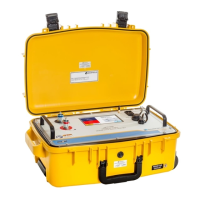
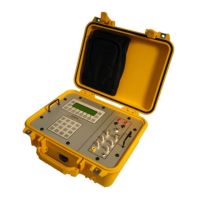
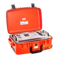
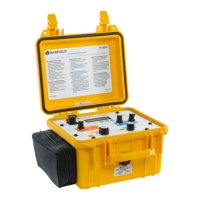
Describes the purpose and application of the DPS1000 Pitot-Static Test Set.
Details the physical and environmental specifications of the test set.
Specifies the acceptable input power voltage ranges for the test set.
Describes the power entry module and its features.
Lists the environmental conditions for operating and storing the test set.
Details the unpacking and assembly of the test set components.
Describes the test set's protective case and its features.
Recommendations for storing the shipping container and packing materials.
Instructions for properly grounding the test set chassis.
Details the power supply cable and its specifications.
Explains the location and importance of unit vents and drainage ports.
Identifies the Pitot and Static quick disconnect ports.
Identifies and explains the front panel switches and controls of the DPS1000.
Advises on proper positioning of the test set for safe operation.
Lists included and not included items such as manuals, cables, and adapters.
Recommends familiarizing with the GUI before connecting to aircraft systems.
Describes the steps and displays during the test set's power-on initialization.
Explains the default mode for measuring and simulating altitude and airspeed.
Describes the mode for airspeed/MACH indicators with static ports vented to ambient.
Details the information shown in the status area (Mode, Limits, Correction, Recovery).
Explains the user interface design for intuitive operation.
Allows users to configure display as 2 or 4-parameter format.
Allows selection of measurement units for display parameters.
Traditional method for setting targets and measuring leak rate.
Automated leak testing using pre-defined or custom profiles.
Resets test set to ambient pressure altitude and CAS = 0 Kts.
Trims pressure offsets for improved low airspeed accuracy.
Enables or disables automatic control mode for high leak rates.
Allows viewing and selecting saved limit file values.
Allows entering altitude difference correction factor.
Allows selecting 2-Channel or 1-Channel Pt-Only control mode.
Allows copying the history log to a USB flash drive for troubleshooting.
Manages custom limit profiles for test parameters.
Allows editing user-created custom limit profiles.
Allows deleting user-created custom limit profiles.
Includes settings for Date/Time, Wi-Fi, and Cabin Pressure Mode.
Instructions for updating HUIM and PCM firmware using a USB drive.
Procedure for changing the user PIN code for menu access.
Allows recalibration of touch screen sensitivity and accuracy.
Options to view current or complete historical event logs.
Allows adjustment of the display backlight intensity.
Steps to perform before powering on and initializing the test set.
Details the process and observations during test set power-on initialization.
Explains the default mode for monitoring pressures and its features.
Explains the controller's function in simulating target pressures.
Steps for connecting hoses and powering on before leak testing.
Introduces Leak Rate Timer and ATP Leak Test methods.
Steps for performing leak test using the Leak Rate Timer.
Instructions for selecting, configuring, and running ATP leak test profiles.
How to apply leak correction to isolate aircraft system leaks.
Ensures test set is safe and connected before aircraft testing.
Performing combined leak tests using the Leak Rate Timer.
Using ATP profiles for combined leak testing.
Steps to ensure test set is ready for aircraft static system testing.
Steps to prepare the test set for aircraft pitot system testing.
Procedures for connecting and configuring for simultaneous Pitot and Static tests.
Steps for conducting MACH tests and constant MACH operations.
Procedure for testing airspeed switches using the Nudge feature.
How to connect and perform Engine Pressure Ratio tests.
Steps to safely shut down the test set after operation.
Procedures for unpacking and inspecting the test set upon receipt.
Guidelines for safely packing and shipping the test set.
Proper methods for storing the test set to maintain its condition.
Manufacturer's recommendations regarding maintenance and repair.
Routine inspections and checks to prevent issues.
Guidance on diagnosing and resolving unit malfunctions.
Information on the calibration interval and authorized facilities.
Defines common abbreviations used in the manual.
Defines default and maximum operating limits for aeronautical parameters.
Visual representation of the internal pneumatic components and flow.
Illustrates the sequence of menus and options within the test set interface.
Steps to enable the cabin pressure testing feature via setup menus.
Describes the process of performing cabin pressure tests on aircraft.
Steps to access and prepare for Inlet Barrier Filter system testing.
Refers to a separate document for the firmware update procedure.
| Brand | barfield |
|---|---|
| Model | DPS1000 |
| Category | Test Equipment |
| Language | English |